Page 36
Installation and Assembly
capaNCDT 6200
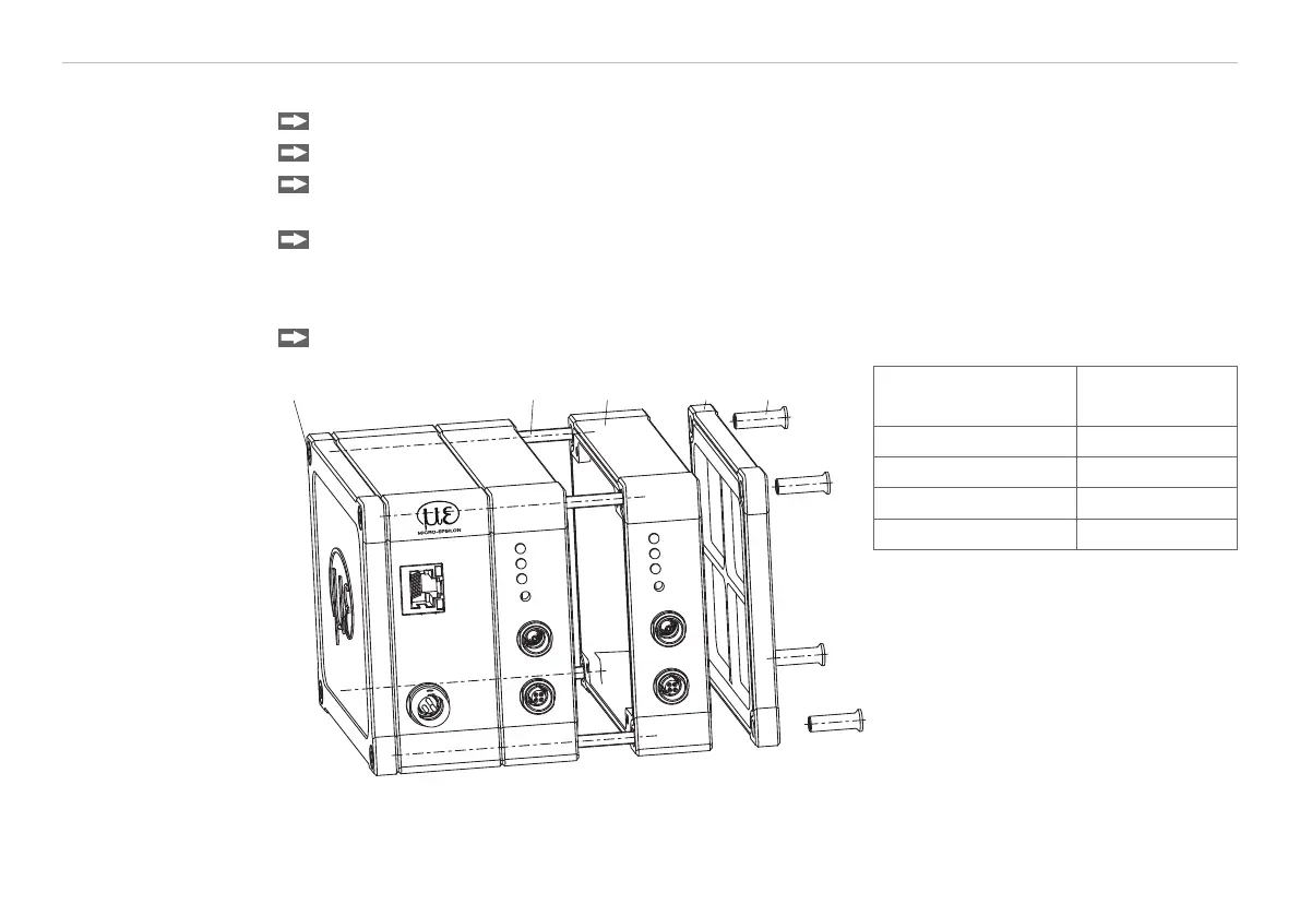
4.5 Insert Demodulator Module
Unscrew the sleeve nuts (4b) on the right side of the controller, remove the right housing cover (3).
Remove a sleeve nut (4a) with threaded rod (1).
Successively replace the threaded rod (1) by a threaded rod next longer from the supplied conversion
kit. Move the new threaded rod with the sleeve nut (4a) through the modules.
Exchange the remaining 3 threaded rods in such a way.
i
Touch the demodulator modules only at the housing, not at the electronics. This will prevent electro-
static discharges on the electronics.
Attach the additional demodulator module.
ETHERNET
POWER/TRIG.
DT6220
DL6220
DL6220
SENSOR/CP
Range
LP Filter
Zero
Zero
SIGNAL OUT
SENSOR/CP
Range
LP Filter
Zero
Zero
SIGNAL OUT
1 4b2 34a
Number demodulator
modules
Length
threaded rod M4
1 59 mm
2 84 mm
3 109 mm
4 134 mm
Fig. 9 Mechanical components control-
ler