Page 37
Installation and Assembly
capaNCDT 6200
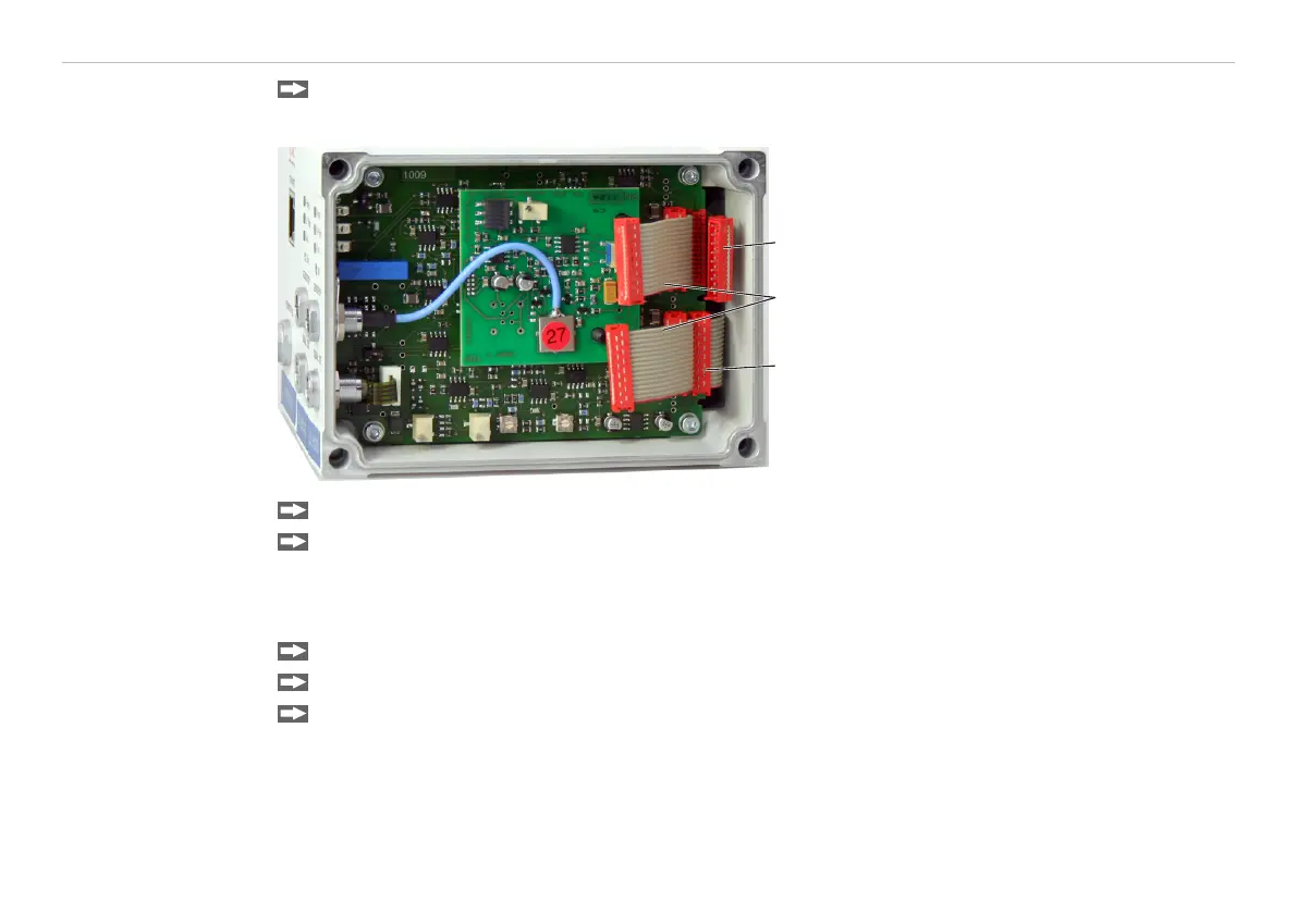
Connect both flat flexible cables (5) of the preceding demodulator module with the new demodulator
module (6).
5
5
6
5 Wiring preceding demodulator
module
6 Wiring following demodulator
module
Fig. 10 Wiring demodulator modules
Put on the right housing cover (3).
Screw the sleeve nuts (4b) on the threaded rods on the right side of the controller and tighten the sleeve
nuts.
The wiring to the preceding demodulator module (5) can be solved using the supplied plugging off assis-
tance as follows:
1. Press the plugging off assistance with the recess laterally to the connector (5).
2. Loosen the connector with a lever movement.
3. Loosen the other side of the connector in the same way.