Page 44
Operation
capaNCDT 6200
5. Operation
5.1 Starting Up
Connect the the display/output devices through the signal output socket, see 4.7, see 4.7.2, see 4.7.3,
before connecting the device to the power supply and switching on the power supply.
i
Allow the measuring system to warm up before the first measurement or calibration for approximately
15 min.
5.2 Operating or Display Elements
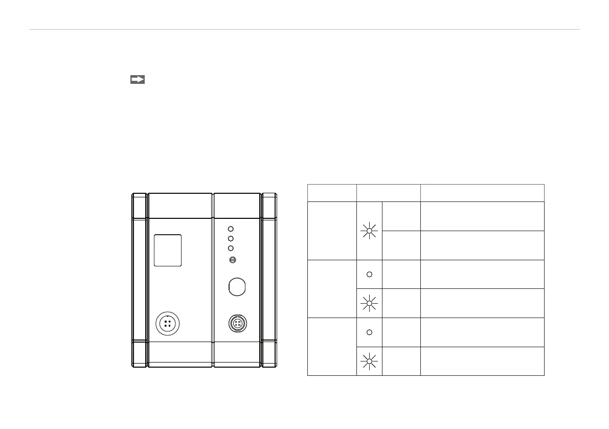
5.2.1 LED‘s
SIGNAL OUT
POWER/TRIG.
ETHERNET
SENSOR/CP
Range
LP Filter
Zero
Zero
LED Color Function
Range
green Target in measuring range
red Measuring range exceeded
LP Filter
1
off Standard bandwidth active
red
20 Hz Low-pass filter on the
analog outputs enabled
Zero
off
Zero poti in basic position
(right stop)
red Zero poti adjusted
1) LP Filter only switchable via Ethernet.