Page 42
Installation and Assembly
capaNCDT 6200
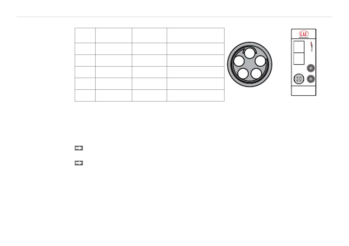
4.7.4 Pin Assignment Synchronization
PIN Assignment Insulation Color
1
2
3
4
5
POWER/TRIG.
OUT
SYNC
IN
ETHERCAT IN ETHERCAT OUT
ETHERNET
1 n.c - -
2 Twisted Pair 1 1 white 1
3 Twisted Pair 1 blue blue
4 Twisted Pair 2 2 white 2
5 Twisted Pair 2 orange orange
SC6000-x is a 0,3 or 1 m long, preassembled synchronization
cable
View on solder pin
side,
5-pin ODU male
cable connector
Sync IN/OUT on
controller, 5-pin female
cable connector
Several measuring systems series capaNCDT 6200 can simultaneously be used as multi-channel system.
With the synchronization of the systems, a mutual influence of the sensors is avoided.
Plug the synchronization cable SC6000-x, see A 1.4, into the female connector SYNC OUT (Synchroni-
sation output) at the controller 1.
Plug the connector of SC6000-x into the female connector SYNC IN (synchronization input) at controller
2.
The oscillator of controller 2 switches automatically into synchronization, this means, depending on the oscil-
lator 1 of Controller 1.
An influence of poor earthed target is excepted.
Synchronize possibly several measuring systems with a SC6000-x.
i
Automatic synchronization. Every controller can be master.