Page 41
Installation and Assembly
capaNCDT 6200
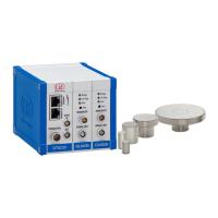
4.7.2 Pin Assignment Supply, Trigger
PIN Color
PC6200-3/4
Signal Description
1
4
2
3
POWER/TRIG.
ETHERNET
DT62xx
1 brown +24VIN +24 VDC Supply
2 white Zero VIN GND Supply
3 yellow TRI_IN+ Trigger IN+, TTL level
4 green TRI_IN- Trigger IN-
shield
PC6000-3/4 is a 3 m (13.12 ft) long, pre-assembled power
supply and trigger cable.
View on solder pin side,
4-pole ODU female
cable connector
Power supply input
on controller, 4-pole
male cable connector
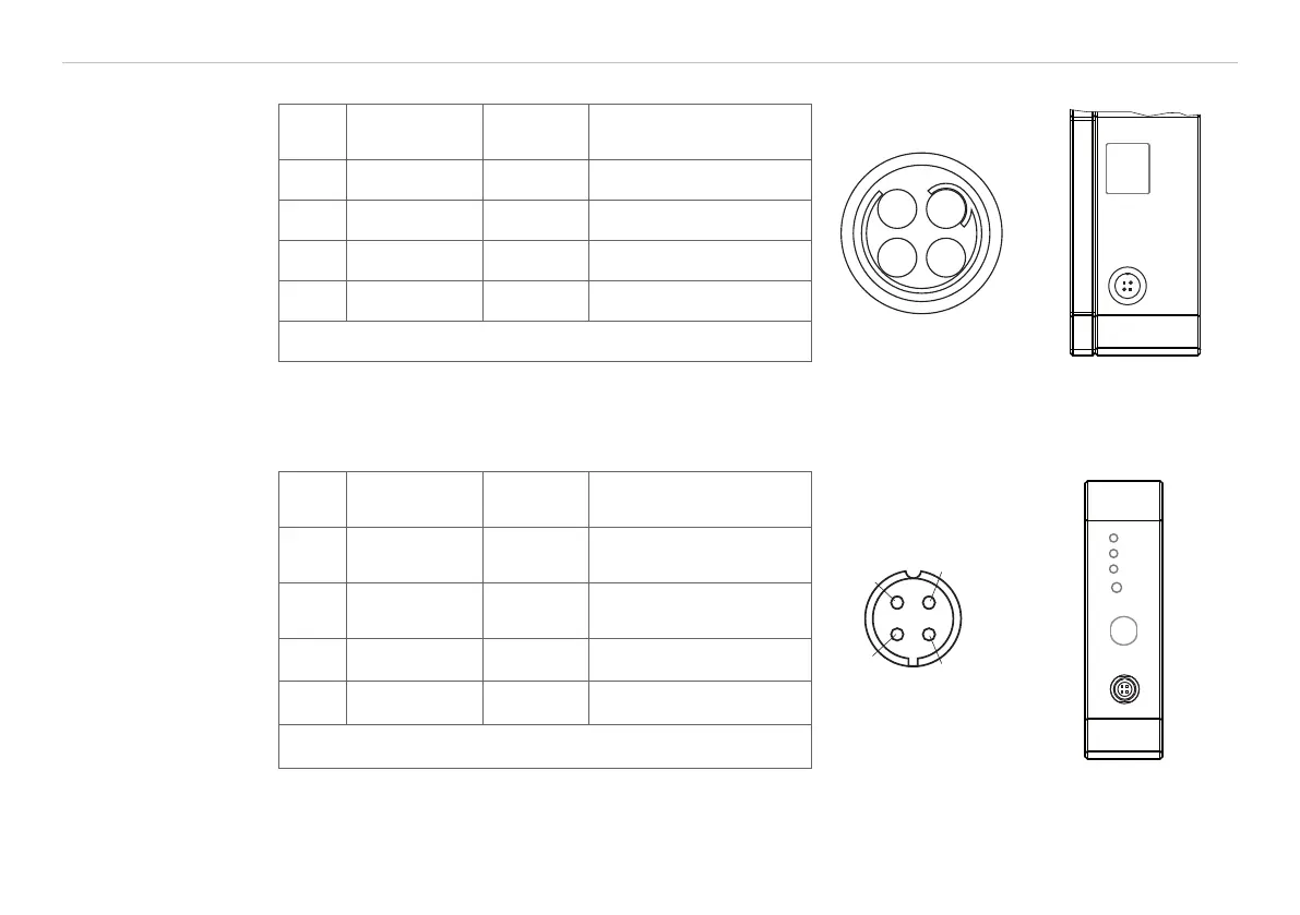
4.7.3 Pin Assignment Analog Output
Pin
Color
SCACx/4
Signal Description
AGND
AGND
I
AUS
U
AUS
SIGNAL OUT
SENSOR/CP
Range
LP Filter
Zero
Zero
DL62xx
1 brown U-out
U
OUT
,
(Load min. 10 kOhm)
2 yellow I-out
I
OUT
,
(Load max. 500 Ohm)
3 gray AGND Analog ground
4 white AGND Analog ground
shield
Analog grounds are connected internally. SCACx/4 is a
3 m (13.12 ft) long, 4-wire output cable. It is supplied as an
optional accessory.
View on solder pin
side, 4-pole male
cable connector
Signal output on con-
troller, 4-pole male cable
connector