Page 77
Ethernet Interface
capaNCDT 6200
6.6 Channel n
6.6.1 Channel Information, Measuring Range
Menu Settings > Channel n > Channel information.
The measuring ranges of the connected sensors must be entered manually. Do not forget to enter the new
range after changing a sensor.
Data channel 1 / 2 / 3 / 4 Value Value range 0 ... 1000000 µm
6.6.2 Linearization
A linearization of a measuring channel (physical demodulator module) may be necessary, if, for example, the
target geometry is changed. Selection of a linearization type depends on how many data points the correc-
tion curve should use.
i
The measuring device requires a run-in period of approximately 15 minutes.
Measuring
channel
1 / 2 / 3 / 4 Linearization type
No linearization / Offset / 2-point / 3-point / 5-point /
10-point
The sequence, with that the linearization points are measured, doesn‘t play a role.
Example: Procedure for a 3 point linearization:
Select the designated measuring channel.
Select a 3-point linearization type.
Adjust the target to 10 % of the measuring range to the sensor.
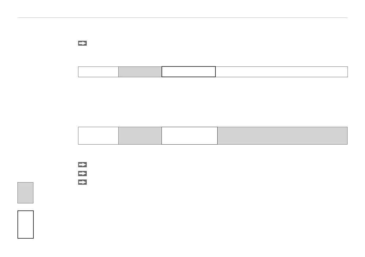
Grey shaded
fields require a
selection.
Value
Dark-bordered
fields require
you to specifie
a value.