dsPIC33/PIC24 Family Reference Manual
DS70005340A-page 100 2018 Microchip Technology Inc.
Figure 10-21 through Figure 10-28 illustrate how the status flags and user address are updated.
The TEF stores transmitted messages; therefore, the flags behave similarly to an RX FIFO.
Figure 10-21 shows the status of the TEF after Reset. Message objects, MO0 to MO11, are
empty. All status flags are cleared. The user address points to MO0.
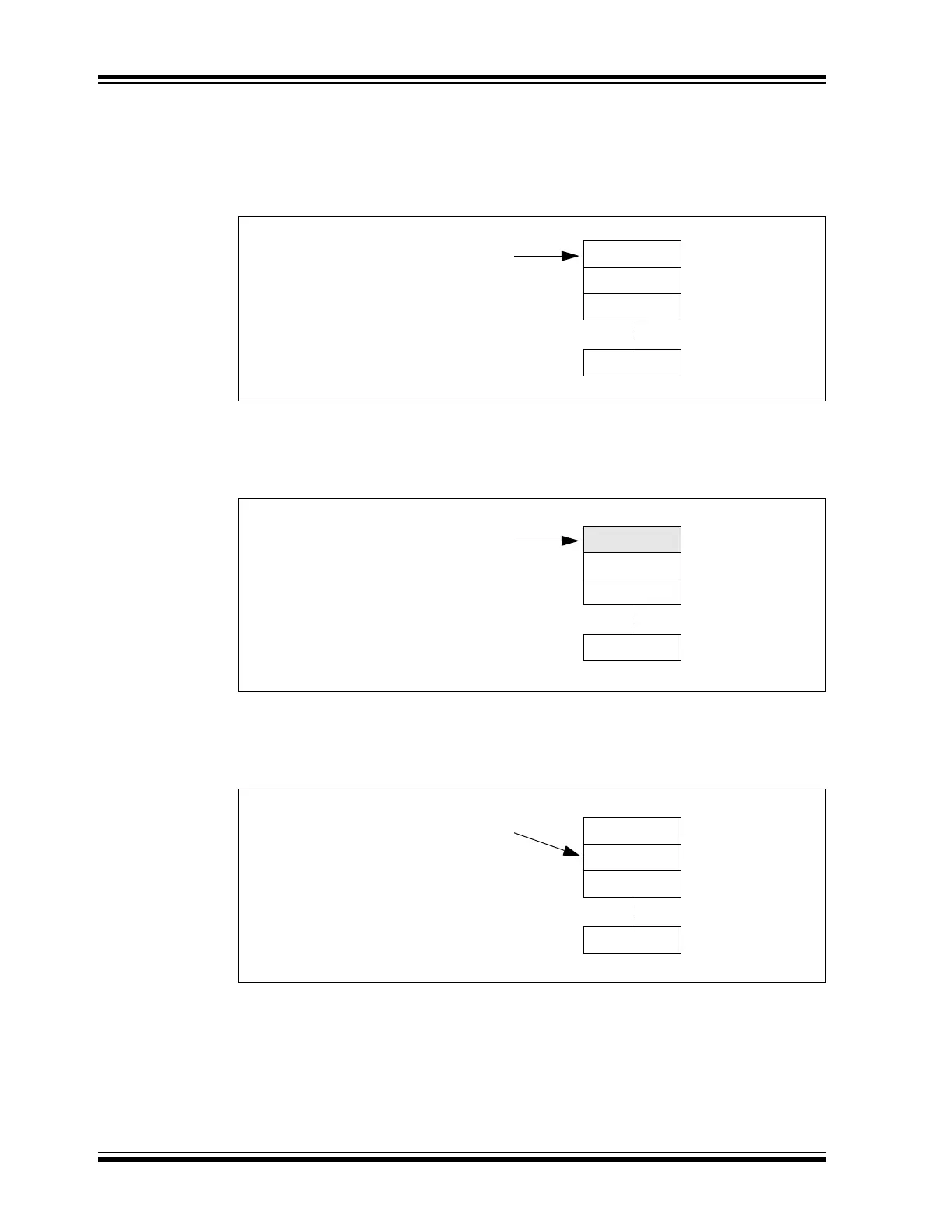
Figure 10-21: TEF – Initial State
Figure 10-22 shows the status of the TEF after the first transmit message is stored. MO0 contains
ID0, the ID of MSG0. TEFNEIF is set since the TEF is not empty. The user address points to
MO0.
Figure 10-22: TEF – First Transmit Message is Stored
Figure 10-23 illustrates the status of the TEF after ID0 is read. The user application reads the ID
from RAM and sets the UINC bit (C1TEFCONL<8>). The user address increments and points to
MO1. The TEF is empty again. All flags are cleared.
Figure 10-23: TEF – First ID Read
MO0
MO1
MO2
MO11
C1TEFUAL = 0x000
C1TEFSTA:
TEFFIF = 0
TEFHIF = 0
TEFNEIF = 0
TEFOVIF = 0
MO0/ID0
MO1
MO2
MO11
C1TEFUAL = 0x000
C1TEFSTA:
TEFFIF = 0
TEFHIF = 0
TEFNEIF = 1
TEFOVIF = 0
MO0
MO1
MO2
MO11
C1TEFUAL = 0x00C
C1TEFSTA:
TEFFIF = 0
TEFHIF = 0
TEFNEIF = 0
TEFOVIF = 0