2018 Microchip Technology Inc. DS70005340A-page 101
CAN FD Protocol Module
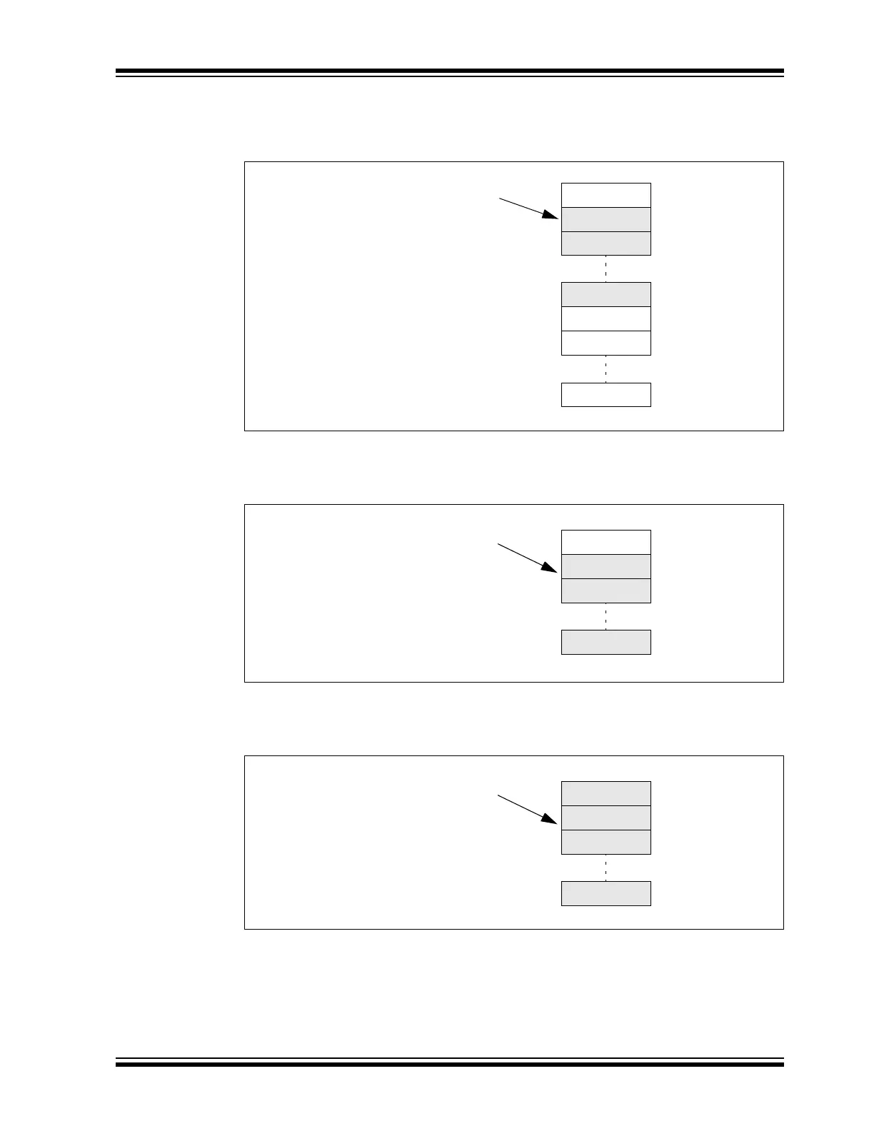
Figure 10-24 illustrates the status of the TEF after six more messages are transmitted: MSG1-MSG6.
The user address points to MO1. TEFNEIF and TEFHIF are set because the TEF is now half full.
Figure 10-24: TEF – Half Full
Figure 10-25 illustrates the status of the TEF after five more messages are transmitted:
MSG7-MSG11. The user address still points to MO1. TEFNEIF and TEFHIF are set.
Figure 10-25: TEF – Almost Full
Figure 10-26 illustrates the status of the TEF after one more message is transmitted: MSG12. All
status flags are set because the TEF is full. The user address points to MO1.
Figure 10-26: TEF – Full
MO0
MO1/ID1
MO2/ID2
C1TEFUAL = 0x00C
C1TEFSTA:
TEFFIF = 0
TEFHIF = 1
TEFNEIF = 1
TEFOVIF = 0
MO11
MO6/ID6
MO7
MO8
MO0
MO1/ID1
MO2/ID2
MO11/ID11
C1TEFUAL = 0x00C
C1TEFSTA:
TEFFIF = 0
TEFHIF = 1
TEFNEIF = 1
TEFOVIF = 0
MO0/ID12
MO1/ID1
MO2/ID2
MO11/ID11
C1TEFUAL = 0x00C
C1TEFSTA:
TEFFIF = 1
TEFHIF = 1
TEFNEIF = 1
TEFOVIF = 0