2018 Microchip Technology Inc. DS70005340A-page 61
CAN FD Protocol Module
5.3.1 SAMPLE POINT
The sample point is the point in the bit time at which the logic level of the bit is read and
interpreted. The sample point in percent can be calculated using Equation 5-7 and Equation 5-8.
Equation 5-7: Nominal Sample Point (%)
Equation 5-8: Data Sample Point (%)
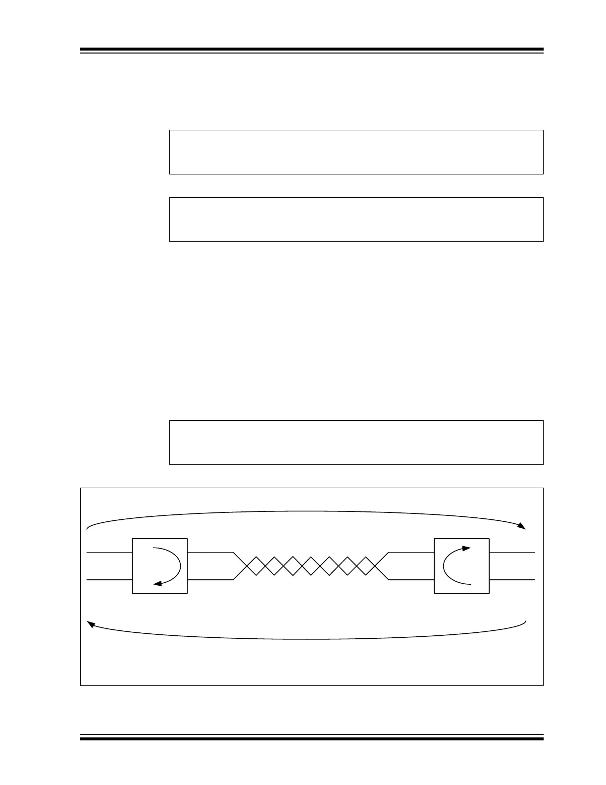
5.3.2 PROPAGATION DELAY
Figure 5-2 illustrates the propagation delay between two CAN nodes on the bus, assuming
Node A is transmitting a CAN message. The transmitted bit will propagate from the transmitting
CAN Node A through the transmitting CAN transceiver, over the CAN bus, through the receiving
CAN transceiver, into the receiving CAN Node B.
During the arbitration phase of a CAN message, the transmitter samples the CAN bus and
checks if the transmitted bit matches the received bit. The transmitting node has to place the
sample point after the maximum propagation delay.
Equation 5-9 describes the maximum propagation delay; where t
TXD – RXD
is the propagation
delay of the transceiver, a maximum of 255 ns according to ISO11898-1:2015; T
BUS
is the delay
on the CAN bus, which is approximately 5 ns/m. The factor 2 comes from the worst case when
Node B starts transmitting exactly when the bit from Node A arrives.
Equation 5-9: Maximum Propagation Delay
Figure 5-2: Propagation Delay
NSP
1NTSEG1+
NBT
NTQ
------------
---------------------------------100=
DSP
1DTSEG1+
DBT
DTQ
------------
---------------------------------100=
T
PROP
T
PROPAB
T
PROPBA
+ 2 t
TXD RXD–
T
BUS
+==
Node A
TXCAN
RXCAN
CANH
CANL
Node B
RXCAN
TXCAN
CANH
CANL
Delay: Node A to B (T
PROPAB
)
CAN bus (T
BUS
)
Transceiver Propagation
Delay (t
TXD-RXD
)
Delay: Node B to A (T
PROPBA
)
Transceiver Propagation
Delay (t
TXD-RXD
)
CxTX
CxRX
Transceiver Propagation
Delay (t
TXD – RXD
)
Transceiver Propagation
Delay (t
TXD – RXD
)
CAN Bus (T
BUS
)
CxRX
CxTX