dsPIC33/PIC24 Family Reference Manual
DS70005340A-page 68 2018 Microchip Technology Inc.
6.3 Loading Messages Into Transmit Queue
Loading transmit message objects into the TXQ works similarly to loading message objects into
a transmit FIFO. The application must check the C1TXQSTA register to see if there is space in
the TXQ. The C1TXQUAH/L registers should be used instead of the C1FIFOUAxH/L registers to
calculate the address to load the message and set the UINC bit (C1TXQCONL<8>) to increment
the head of the TXQ.
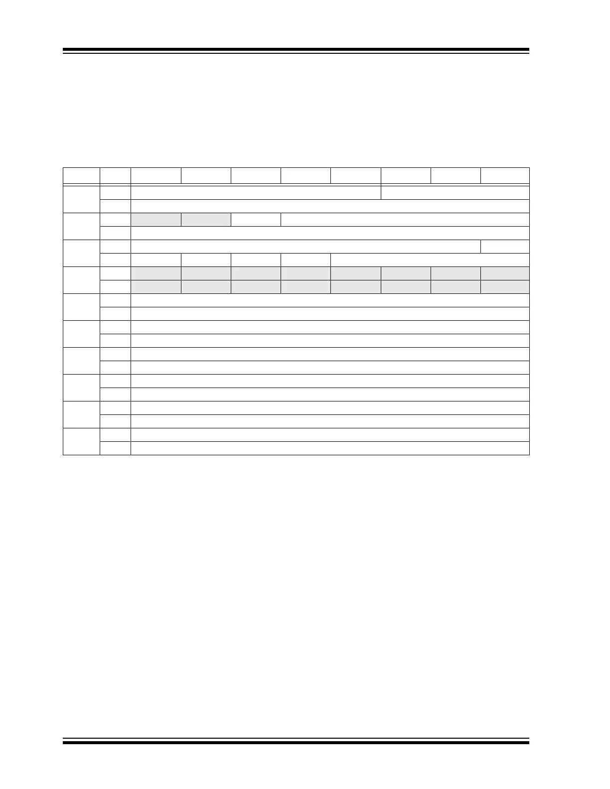
Table 6-1: Transmit Message Object (TXQ and TX FIFO)
Words Bits Bit 15/7 Bit 14/6 Bit 13/5 Bit 12/4 Bit 11/3 Bit 10/2 Bit 9/1 Bit 8/0
T0
15:8 EID<4:0> SID<10:8>
7:0 SID<7:0>
T1
15:8
— — SID11 EID<17:13>
7:0 EID<12:5>
T2
15:8 SEQ<6:0> ESI
7:0 FDF BRS RTR IDE DLC<3:0>
T3
15:8 — — — — — — — —
7:0
— — — — — — — —
T4
(1)
15:8 Transmit Data Byte 1
7:0 Transmit Data Byte 0
T5
(1)
15:8 Transmit Data Byte 3
7:0 Transmit Data Byte 2
T6
15:8 Transmit Data Byte 5
7:0 Transmit Data Byte 4
T7
15:8 Transmit Data Byte 7
7:0 Transmit Data Byte 6
Ti-1
15:8 Transmit Data Byte n-3
7:0 Transmit Data Byte n-2
Ti
15:8 Transmit Data Byte n
7:0 Transmit Data Byte n-1
bit 15:11 (T0) EID<4:0>: Extended Identifier bits
bit 10-0 (T0) SID<10:0>: Standard Identifier bits
bit 15-14 (T1) Unimplemented: Read as ‘x’
bit 13 (T1) SID11: In FD mode, the Standard ID can be extended to 12 bits using r1
bit 12-0 (T1) EID<17:5>: Extended Identifier bits
bit 15-9 (T2) SEQ<6:0>: Sequence to keep track of transmitted messages in transmit event FIFO bits
bit 8 (T2) ESI: Error Status Indicator bit
In CAN to CAN Gateway mode (ESIGM (C1CONH<1>) = 1), the transmitted ESI flag is a “logical OR”
of ESI (T1) and the error passive state of the CAN controller.
In Normal mode, ESI indicates the error status:
1 = Transmitting node is error passive
0 = Transmitting node is error active
bit 7 (T2) FDF: FD Frame bit; distinguishes between CAN and CAN FD formats
bit 6 (T2) BRS: Bit Rate Switch bit; selects if Data Bit Rate is switched
bit 5 (T2) RTR: Remote Transmission Request bit; not used in CAN FD
bit 4 (T2) IDE: Identifier Extension bit; distinguishes between base and extended format
bit 3-0 (T2) DLC<3:0>: Data Length Code bits
bit 15:0 (T3) Unimplemented: Read as ‘x’
Note 1: Data Bytes 0-n: Payload size is configured individually in the PLSIZE<2:0> bits (C1FIFOCONxH<15:13>).