PICkit™ 3 Starter Kit User’s Guide
DS41628B-page 70 2012 Microchip Technology Inc.
Both devices are using some features of the enhanced PWM module. The PIC16 will
operate the CCP module in single output since the CCP2 P2A pin connects directly to
DS4. The PIC18 will operate the CCP module in Full-Bridge mode in order to modulate
P1D on DS3.
Maximum resolution is achieved when the PRx register is set to 0xFF, or rather 255,
the maximum value an 8-bit number can hold.
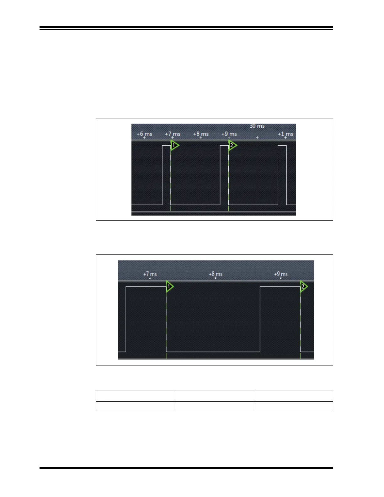
Below is a scope capture of the PWM signal when the LED is dimly lit. As one can see,
the Period is around ~2 ms, with the pulse width being only few hundred us wide.
FIGURE 3-9: SMALL PULSE WIDTH
Figure 3-10 shows when the dial is turned 30% clockwise. Notice how the pulse width
is greater than that shown in Figure 3-9, and that the frequency did not change.
FIGURE 3-10: GREATER PULSE WIDTH
TABLE 3-29:
Instruction English Purpose
andlw And a literal with WREG Masking values