Lessons
2012 Microchip Technology Inc. DS41628B-page 75
The firmware within the Interrupt Service Routine (ISR) should determine the source of
the interrupt by polling the interrupt flag bits. The serviced interrupt flag bits must be
cleared before exiting the ISR to avoid repeated interrupts. Because the GIE bit is
cleared, any interrupt that occurs while executing the ISR will be recorded through its
interrupt flag, but will not cause the processor to redirect to the interrupt vector until the
retfie instruction is executed, thereby enabling the GIE bit.
3.11.3.2 WEAK PULL-UPS
Both the enhanced mid-range and PIC18 devices in this tutorial are able to provide
internal pull-up resistors on some pins. This can greatly reduce the need of external
hardware.
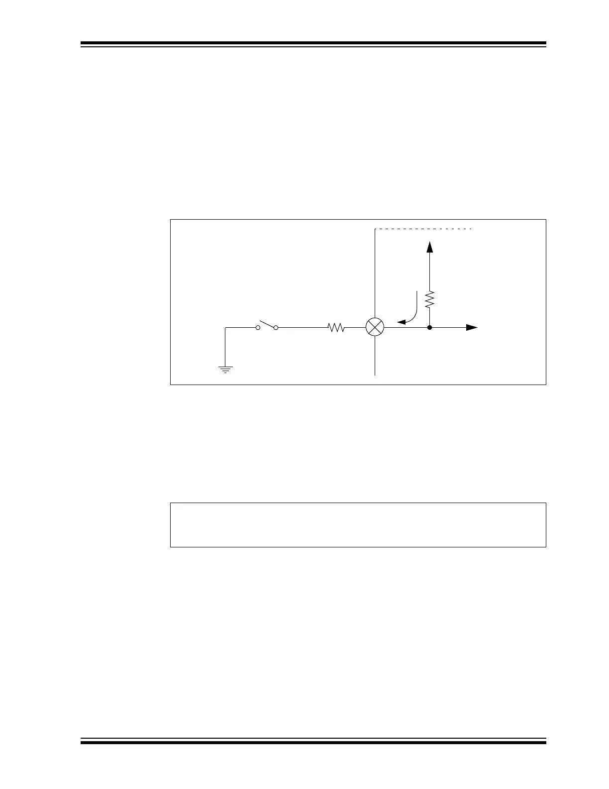
FIGURE 3-12: WEAK PULL-UP DIAGRAM
As seen in Figure 3-12, by enabling the weak pull-up on a pin, the pin will always read
a ‘1’ if no other external circuitry is connected to RA2. In this demo, there is a resistor
connected to the switch, which is then connected to ground. When the switch is
pressed, the voltage on RA2 is no longer V
DD, but rather close to 0V, or ground.
The pull-up resistor is not given a value in the electrical specifications, but rather the
current, Ipur. For the PIC16F1829, this is typically 140 µA. When the switch is closed,
given the typical current spec, the voltage on RA2 becomes:
EQUATION 3-4:
It is called a “weak” pull-up since it does not bring the pin to V
DD quickly. A stronger
pull-up would have a low resistance and bring the pin quickly up to V
DD. If there is a fair
amount of capacitance on the pin, the pin may take a while to register as logic-high to
the PIC MCU. Since it is a weak pull-up, the designer can easily override this internal
setting by using an external resistor, typically in the range of 1k-10k, to change the pin’s
state.
VDD
R2
Rpull-up
To P IC
®
MCU
SW1
GND
Irp
RA2
VI * R=
VA3 140 * 10
6–
* 2k 28mV==