3 Design Integration Considerations
This section provides information on mounting and mating connectors, operating temperature,
electrical interface, and noise susceptibility.
3.1 Mechanical Considerations
To mount the SA.22c to a custom-designed circuit board, use the SAMTEC mating connector (see SA.22c
).Dimensions (see page 4)
Note: For more information on an adapter test board and designing your own interface circuit board,
contact Microsemi sales representatives.
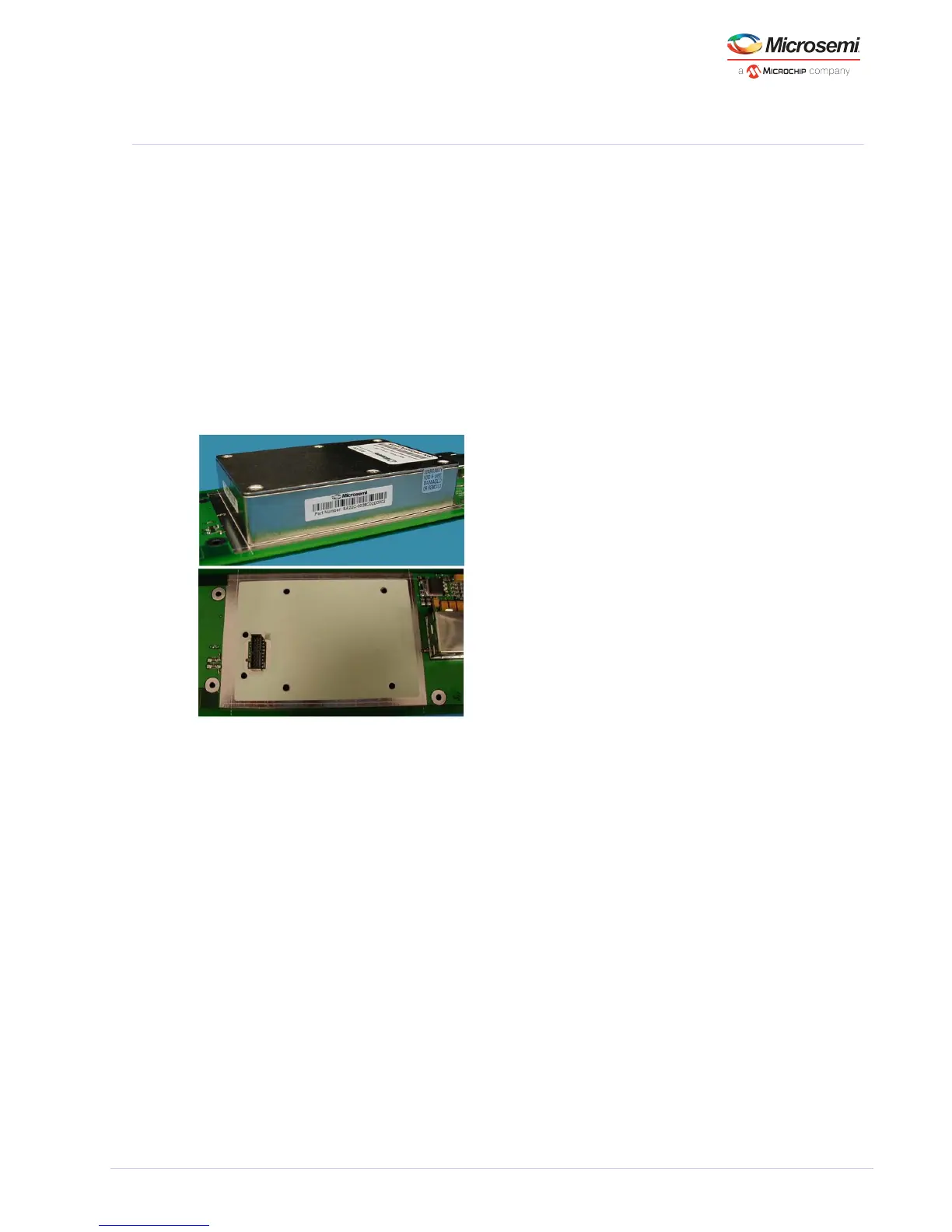
The following figure shows how to mount SA.22c to a circuit board. Mount the SA.22c to the circuit
board using six M3 stainless steel screws with a minimum penetration depth of 2 mm and a maximum of
5 mm.
Figure 6 • Mounting an SA.22c to a Circuit Board
3.2 Environmental Considerations
The following sections provide design considerations regarding thermal, humidity, and dust challenges.
3.2.1 Thermal Tape
The base plate of the SA.22c must have good thermal contact to the mounting surface so that the
operating base plate temperature can achieve the highest ambient operating temperature. The
mounting points of the base plate must maintain uniform temperature. The SA.22c unit normally
operates without the thermal tape. However, in some field applications, the tape simplifies the
customer system thermal design requirements.
Warning: Attach the SA.22c to a heat sink to prevent it from becoming too hot.
If there is an air flow over the unit's top cover, the SA.22c's maximum operating base plate temperature
increases by 1 °C or 2 °C and the power consumption at a given base plate temperature also increases
by a few tens of milliwatts. As the base plate temperature continues to increase, the unit eventually
loses lock.
Above a base plate temperature of 75 °C, the resonator or lamp heaters get shut down as the control
point temperatures are exceeded and the unit temperature coefficients increase to approximately
6 × 10 °C.
–10