5 Appendix: Using the Developer’s Kit
This appendix provides information about using the SA.22c developer’s kit. It includes information about
interfacing the adapter test board and the various options for providing power and viewing signals from
the SA.22c through the adapter test board.
The SA.22c developer's kit is provided by Microsemi as a design aid and development tool. It allows you
to experiment with the Microsemi SA.22c product in various applications and determine how to
implement it in the most advantageous manner.
The developer's kit contains a hard copy of this document, the SA.22c unit, the adapter test board, an
optional heat sink, application notes, and a CD with electronic files documenting the specifications and
performance of the unit.
Note: Contents of the Developer's Kit may change. Consult the packing list for an up-to-date list of
materials.
Note: Use a power supply with leads or interface cable to connect the adapter test board to the main
power. To avoid potential damage to the adapter test board and the SA.22c, ensure that correct polarity
is used.
5.1 Mounting the Unit with the Adapter Test Board
The SA.22c, along with the adapter test board, is designed to mount on a heat-absorbing surface. If a
heat-absorbing surface is not available for testing, a suitable heat sink can be ordered as an option.
Note: The mounting screws of the SA.22c are metric (not SAE) and are 3 mm in length with a 0.5 mm
thread pitch. They must not penetrate more than 3 mm into the SA.22c base plate.
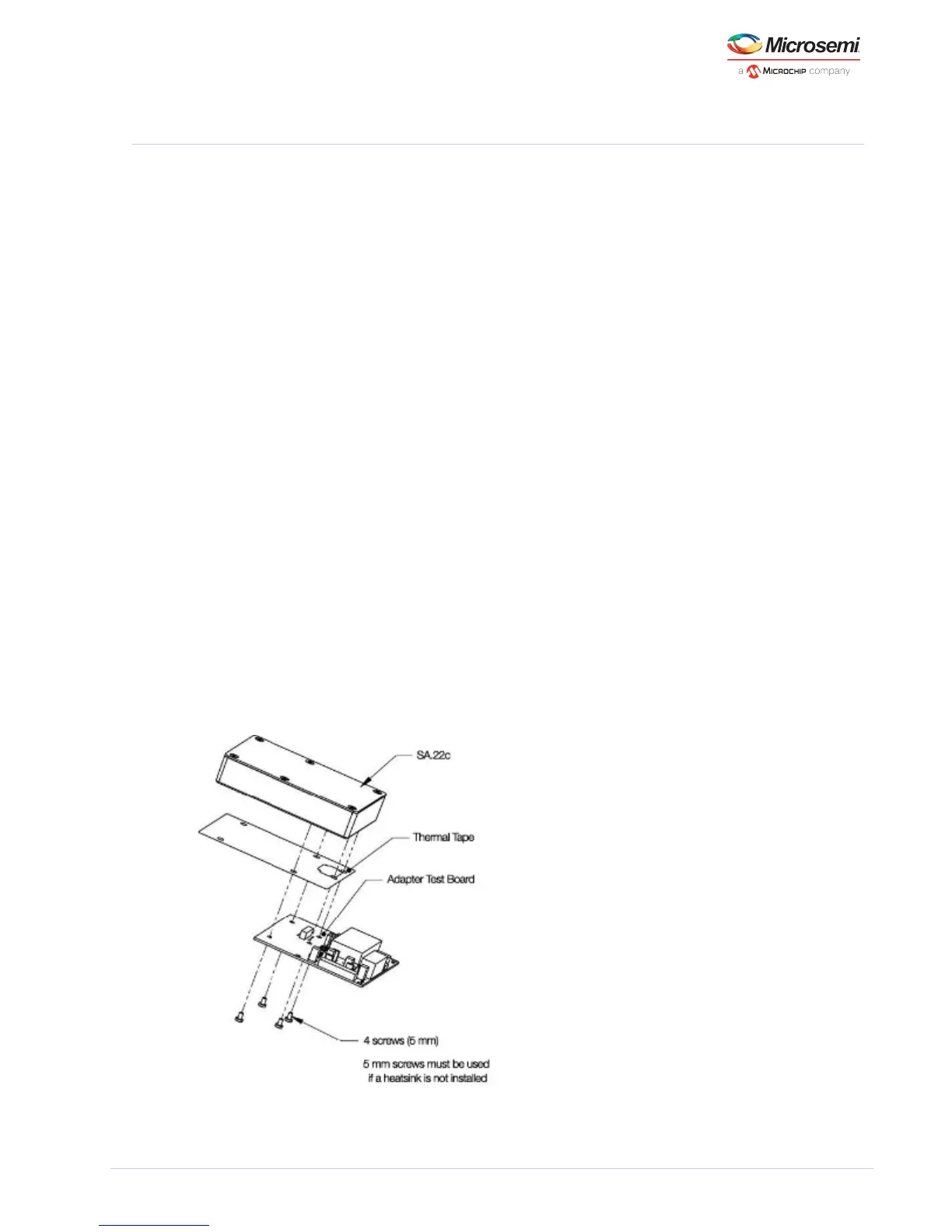
The following illustration shows the mounting of the SA.22c on the adapter test board. Four 5 mm
screws are required to mount the SA.22c on the adapter test board if the optional heat sink is not used.
Note: To achieve and maintain the highest level of performance for the SA.22c, Microsemi recommends
utilizing a suitable means for heat sinking if you choose not to purchase the optional heat sink.
Figure 10 • SA.22c Developer’s Kit without Heatsink Assembly