2.2 Specifications
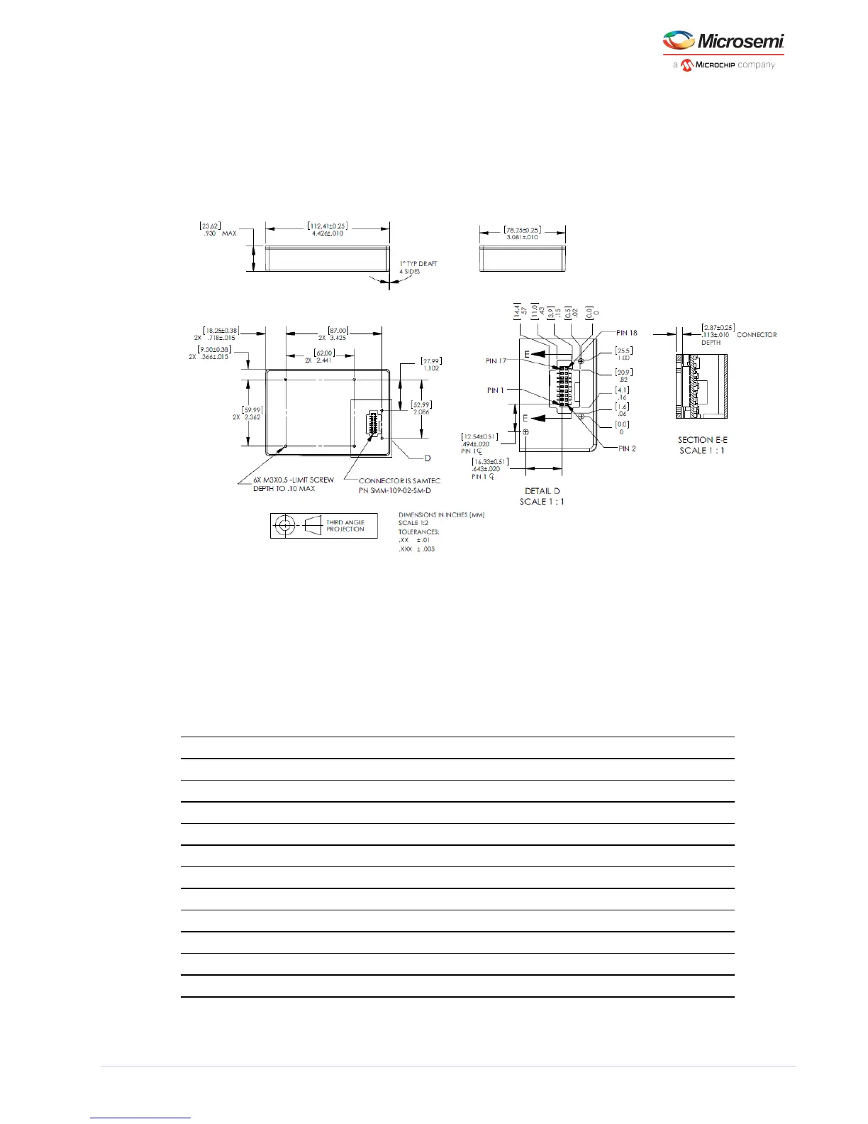
The following figure provides the detailed mechanical specifications of SA.22c.
Note: Datasheet specifications take precedence over this document.
Figure 3 • SA.22c Dimensions
Note: The mating connector is a SAMTEC TMMH-109-01-G-DV-ES-A 2 X 9 shrouded header.
Caution: To avoid damage to the SA.22c, ensure that power and ground are properly connected.
Note: All pins on the I/O connector must be connected.
The following table provides information on the pin assignment and the function chart for SA.22c.
Table 1 • SA.22c Pin Assignment and Function Chart
Pin Signal Type Function
1 VSS GND Power and signal return ground (all ground pins must be connected)
2 VDD PWR 15 Vdc power input (all power pins must be connected)
3 VSS GND Power and signal return ground (all ground pins must be connected)
4 VDD PWR 15 Vdc power input (all power pins must be connected)
5 FREQ CTRL Analog Frequency control. Analog input between 0-5 Vdc
6 VCC PWR 5 Vdc power input
7 1PPS OUT Output 1PPS output, may be enabled/disabled digitally
8 VSS GND Power and signal return ground (all ground pins must be connected)
9 FACMOS Output (FACMOS) ACMOS output (frequency selectable at factory)
10 VSS GND Power and signal return ground (all ground pins must be connected)
11 VSS GND Power and signal return ground (all ground pins must be connected)