The following figures show the block diagrams of the three different options for powering and setting up
the SA.22c with the adapter board. It also shows the connections used to access various inputs and
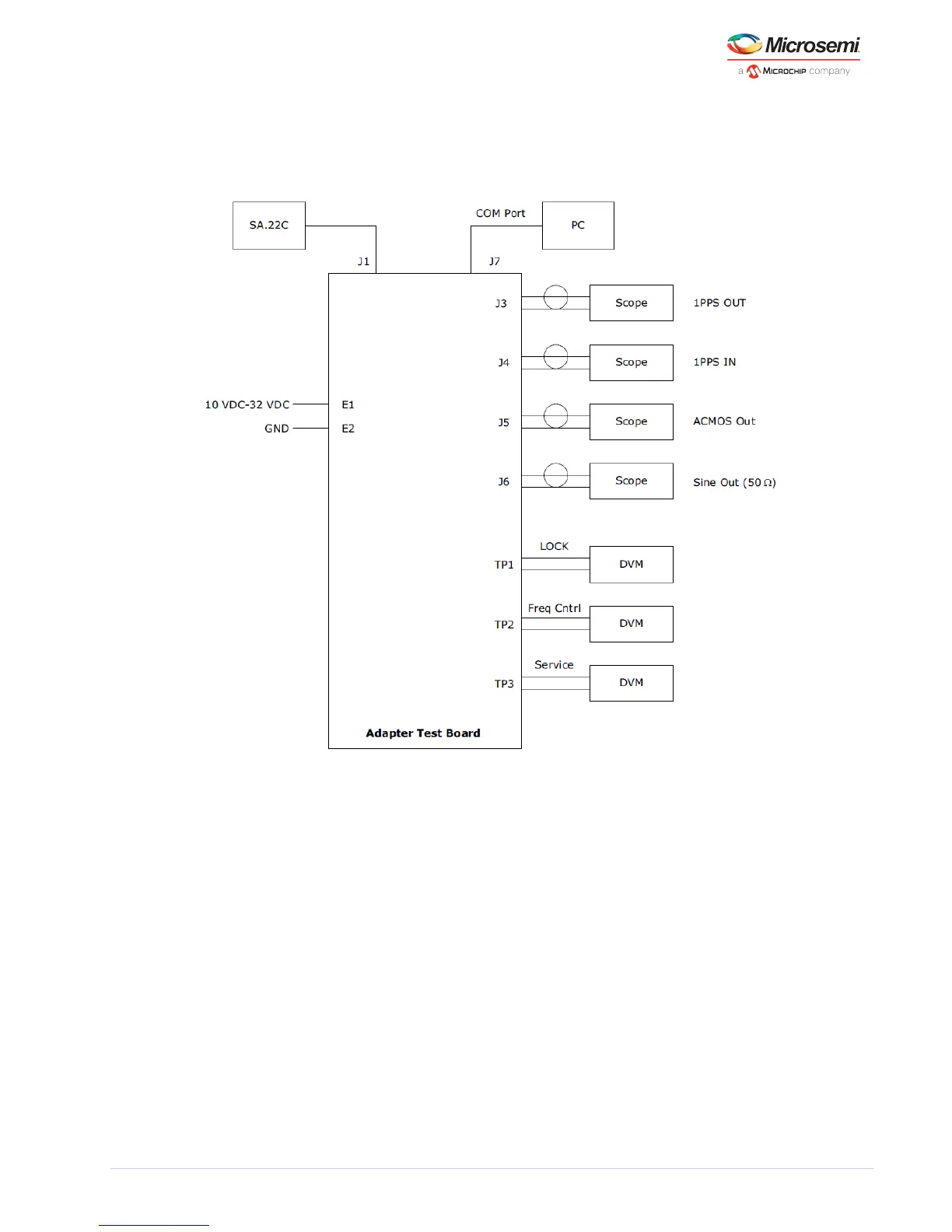
outputs of the SA.22c depending on the option selected.
Figure 13 • Block Diagram of Suggested Test SA.22C Set-up (Option 1)
After the SA.22c unit receives power, wait for a few minutes while the unit achieves atomic lock. During
this period, the monitored lock signal must be HIGH. After the unit achieves atomic lock, the lock signal
goes LOW.