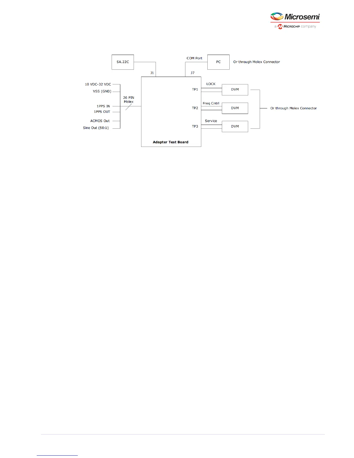
Figure 15 • Block Diagram of Suggested Test SA.22C Set-up (Option 3)
After the SA.22c unit receives power, wait for few a minutes while the unit achieves atomic lock. During
this period, the monitored lock signal must be HIGH. After the unit achieves atomic lock, the lock signal
goes LOW.
The following figure shows the physical power supply wiring and jumper settings needed for each
option.
Warning: Use the power settings and connectors that are appropriate for one particular option at a
time. Mixing any combination of these options may result in system failure and may cause damage to
the existing circuitry.