- 15 -
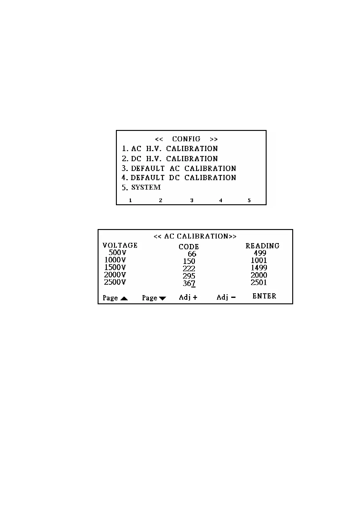
calibrating display as figure 13. On the left side of the display is voltage set value,
voltage calibration code in the middle, and voltage measured value on the right side. At
beginning, the cursor makes a stop on the row of 500V and corrects the voltage by S3
(plus correction code) and S4 (minus correction code); after correcting measured value
to the set value approximation, press S5, jump to the next row and to do the other
correction. By this procedure to correct voltages to 2500V, press S5 and the cursor will
back to the row of 500V again. In this moment, you can press S2 passing to next page
and do another correction. When all voltage corrections are done, press EXIT to leave
the display, and high voltage code would be saved automatically.
Figure 12
Figure 13
Option 2 is DC high voltage calibration. The setting procedure is the same as AC
calibration.
Option 3 and 4 are load default AC and DC calibration value. Press S3 or S4 in system
configuration display, and display would show up “correction codes will be lost”. Press
ENTER to turn correction codes into default ones; on the other hand, press EXIT to quit
without change.
Option 5 System setting:
Press button S5 to enter system setting page (figure 12).
There are four options in this page, and the functions of these options are described as
following:
1st option: The multi-test setting for NG products. Press S1 button to change status
between STOP and CONTINUE. When status is STOP, the tester will stop testing if NG