Manual Number 9018233 Revision C, February 21, 2022 11
SECTION 3 INSTALLATION
3.1 GENERAL INFORMATION
This section contains interconnect diagrams, mounting dimensions and other information pertaining
to the installation of the MD302 SAM Standby Attitude Module. After installation of cabling and
before installation of the equipment, ensure that power is applied only to the pins specified in the
interconnect diagram.
IMPORTANT: READ THIS ENTIRE SECTION PRIOR TO STARTING INSTALLATION!
3.2 PARTS LIST
When unpacking this equipment, make a visual inspection for evidence of any damage that may
have incurred during shipment. The following parts should be included:
Item Description MCIA Part Number
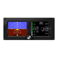
a. MD302 SAM Standby Attitude Module 6420302-3
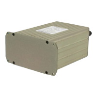
i. Internal/Replacement Battery Pack 9017177 (Type 1)
(Installed on select versions) 9019120 (Type 2)
ii. Included/Replacement O-rings 9017146
b. Installation Manual 9018233
c. Connector Kit 9017646-1
i. Nutplate 9017490-2
ii. Pneumatic Connector (x2) 9017642
iii. Screw, Hex, 6-32x5/8 (x4) 90-620-52011
iv. Screw, Flat, 2-56x1/4 (x2) 90-208-10011
v. Configuration Module 9017275
1. 15-pin D-Sub
2. Backshell
3. Backshell Cover
4. Printed Circuit Board Assembly
5. Screw, Flat, 2-56x1/4 (x2)
6. Screw, 4-40x3/16 (x4)
3.3 CABLE HARNESS
Construct the cable harness in accordance with the instructions below including the Connector
Pinout of Table 2.1 and Figure 2.3 and Configuration Module Assembly of Figure 2.4. Installers
should follow industry-accepted practices regarding aircraft wiring and applicable regulatory
requirements and guidance. The instructions for constructing the cable harness as listed within this
manual were also used to construct the harness during environmental and electrical testing.
Alterations may invalidate environmental qualification and/or performance results.
Refer to Section 2.1, Equipment Location for routing precautions.