Manual Number 9018233 Revision C, February 21, 2022
14
9) Loosely connect the two halves of the Cable Strain Relief Clamp with (2) screws (Item 8).
10) Place the Cable Strain Relief Clamp in the Backshell as shown.
11) Bend the wires of the Configuration Module PC Board Assembly 180 degrees so that the
PC Board has its electrical components facing down as shown. Be careful not to place
excess strain on the solder connections between the wires and the PC Board.
12) Capture the Configuration Module PC Board Assembly into the Backshell by placing the
Backshell Cover (Item 2) on top of the Backshell.
13) Secure the Backshell Cover onto the Backshell using (2) Screws (Item 9).
14) Bundle the exposed shield braids and secure them to either threaded hole on the rear of
the Backshell using a 2-56 screw (Item 10). A wire that is common to aircraft chassis
ground shall also be connected to one of these two holes on the Backshell. Use of a ring
terminal (not included) may be useful.
15) The completed assembly should look as shown. Verify that the Slide Lock operates freely
and that no wires are pinched, nicked, or otherwise damaged.
Verify that power and ground signals are installed appropriately before connecting to the unit.
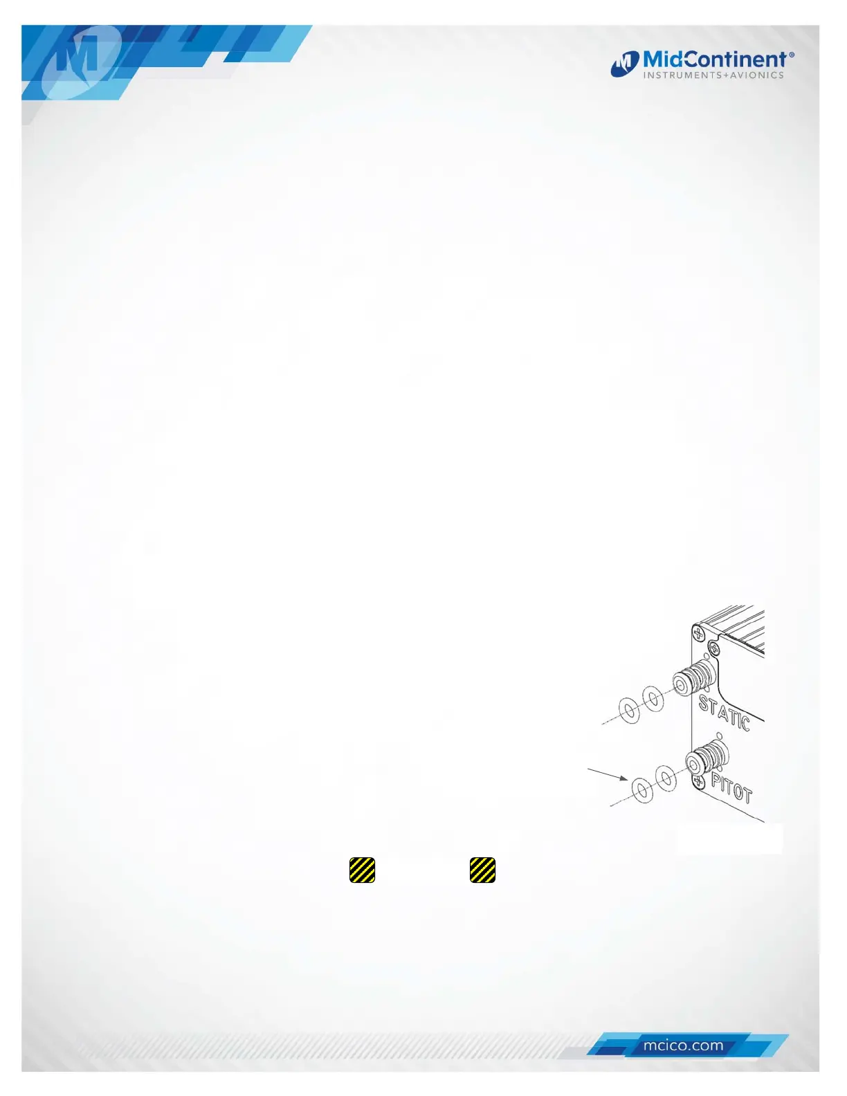
3.4 PITOT / STATIC CONNECTIONS
The connector kit supplied with the unit contains two (2) pneumatic quick disconnect fittings. These
fittings are specific to the connections on the rear of the unit and required for proper operation.
Aircraft tubing that connects to the unit must be ¼” OD with an
approximate 0.17” ID. When determining tubing length, be sure that it
can extend through the cutout in the panel by approximately 8” to allow
the unit to be installed and removed from the front of the panel.
If o-rings are worn or damaged, replace with MCIA p/n 9017146 and
install per the drawing as shown.
NOTE: It is helpful to identify/label each tube (pitot or static) so that it can be
connected to the correct port on the back of the unit during installation.
CAUTION: Lock quick disconnect before connecting to the unit to avoid damaging the O-ring.
CAUTION
MCIA p/n 9017146
(x4)
(rear of unit)