Manual Number 9018233 Revision C, February 21, 2022
13
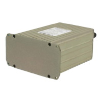
To assemble the aircraft cable harness and Configuration Module refer to the following
instructions and Figure 3.2:
1) Install a pin/socket as supplied in the Connector Kit using an appropriate crimping tool for
each wire in the aircraft cable harness. Be sure to make the harness long enough to
remove the unit from the front of the panel without stressing the harness (approx. 8” longer
than required to reach the unit connector).
2) Braids from shielded wires should be separated from the wire conductors and pulled back
from the pin/socket termination approximately 2” and gathered together.
a. NOTE: Additional chafe protection, such as heat shrink or nylon wire braid is
recommended over the bundle (not including the shields) to prevent wear when
installed in the cable clamp.
3) Insert the pins of the cable harness into the rear of the 15-pin D-Sub connector (Item 4) per
Table 3.1 and Figure 3.1 using an appropriate pin insertion tool.
The Configuration Module PC Board Assembly contains sensitive electronics that
can be damaged by electrostatic discharge (ESD). Appropriate precautions should
be applied prior to handling this component.
4) Insert the pins of the Configuration Module PC Board Assembly (Item 3) into their
corresponding locations as noted below using an appropriate pin insertion tool.
a. The wires coming from the Configuration Module PC Board Assembly are marked as
follows on the circuit board: TP1, TP2, TP3, TP4.
b. With the D-Sub oriented up (pin locations 1-5 on top), orient the Configuration
Module PC Board Assembly with the electronic parts facing UP prior to pin insertion.
c. Install each pin into the rear of the D-Sub connector as follows:
Board TP1 = config return = D-Sub pin 15
Board TP2 = config data = D-Sub pin 14
Board TP3 = config clock = D-Sub pin 10
Board TP4 = config power = D-Sub pin 5
5) Install the D-Sub Backshell Spring (Item 5) as shown.
6) Place the D-Sub Slide Lock (Item 6) over the D-Sub connector.
7) Install the D-Sub connector with Slide Lock and cable harness attached into the Backshell
(Item 1) and secure with (2) screws (Item 8). Verify that the Backshell Spring is between
the Slide Lock and Backshell. Move the Slide Lock back and forth to verify free movement.
8) Route the aircraft wire harness bundle (excluding shield braids) between the two halves of
the Cable Strain Relief Clamp (Item 7). The Clamp should be placed over the chafe
protection installed in Step 2 (if used).
CAUTION