Manual Number 9018233 Revision C, February 21, 2022
12
Wire Gauge Selection
Wire gauge should be 22 AWG. Use of PTFE, ETFE, TFE, Teflon, or Tefzel insulated wire is
recommended for aircraft use per MIL-DTL-16878 or equivalent. Additionally, for data signals
associated with ARINC 429 inputs and outputs, shielded twisted pair wiring per M27500 or
equivalent is recommended (pin pairs 3 & 8 and 12 & 13).
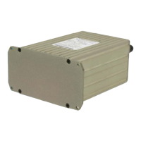
Configuration Module
The supplied custom configuration module is required for proper installation and operation of the
unit. The functions associated with the 15-pin D-subminiature connector are identified as follows:
Unit Connector Pin Identification
Pin No. Description Pin No. Description
1 +10-32VDC Input 9 Reserved
2 Valid Signal Out 10 Config Module Clock
3
RINC Out B 11 Reserved
4 Reserved 12
RINC In
5 Config Module Powe
13
RINC In B
6 Power Return / Ground 14 Config Module Data
7 Reserved 15 Config Module Return
8
RINC Out
TABLE 3.1
UNIT CONNECTOR PIN IDENTIFICATION
FIGURE 3.1
VIEW FROM REAR OF MATING CONNECTOR