MCAC-VTSM-2014-10 R410A All DC Inverter Mini VRF
Troubleshooting 83
For example:
Press the button for 5 seconds:
If the “running” and “warning” lights are normally on, that means the address code is 9=(8+1)
If the lights are blink, the address code should plus 16, so the address code is 25=16+(8+1)
Press the button for 10 seconds:
If the “timer” and “warning” lights are normally on, that means the capacity code is 5=(4+1) and the capacity
of indoor unit is 71×100W(2.5HP).
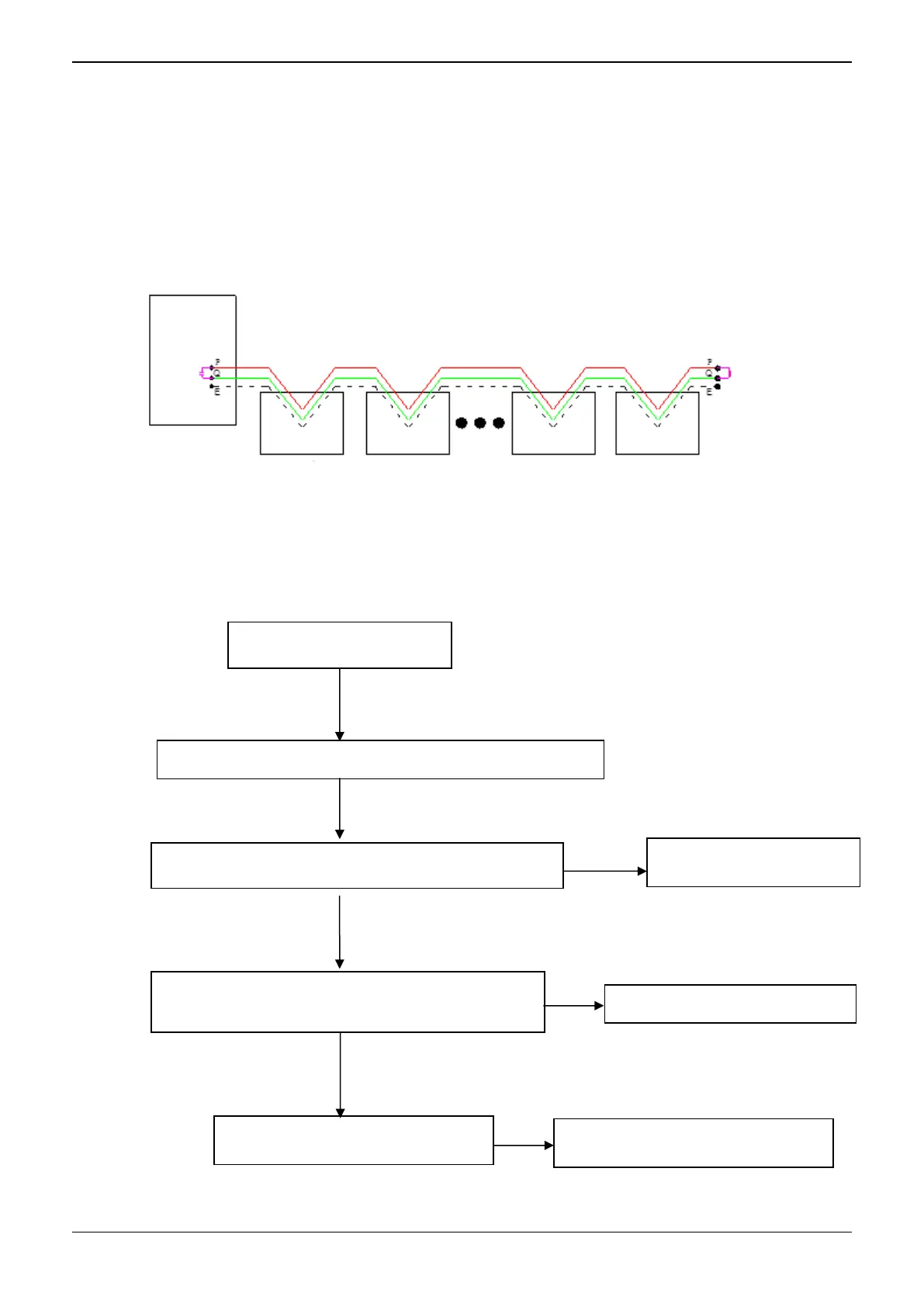
2. If the signal is weak, connect a 120Ω resistor between P and Q of the farthest indoor unit, or connect a
0.5-1.5uF capacitor between P and Q of outdoor unit. Installation refers to the following picture:
Note:
Communication wires should be shield wire and indoor units should be connected in series.
7.3 E4: Pipe temperature T3& ambient temperature T4 sensor malfunction (for all models)
Whether the wire body is broken.
Pipe temperature T3& ambient temperature T4 sensor
malfunction
Judge whether temperature sensor pin connects
properly.

 Loading...