Outdoor Unit Disassembly 35
2. PCB board 2
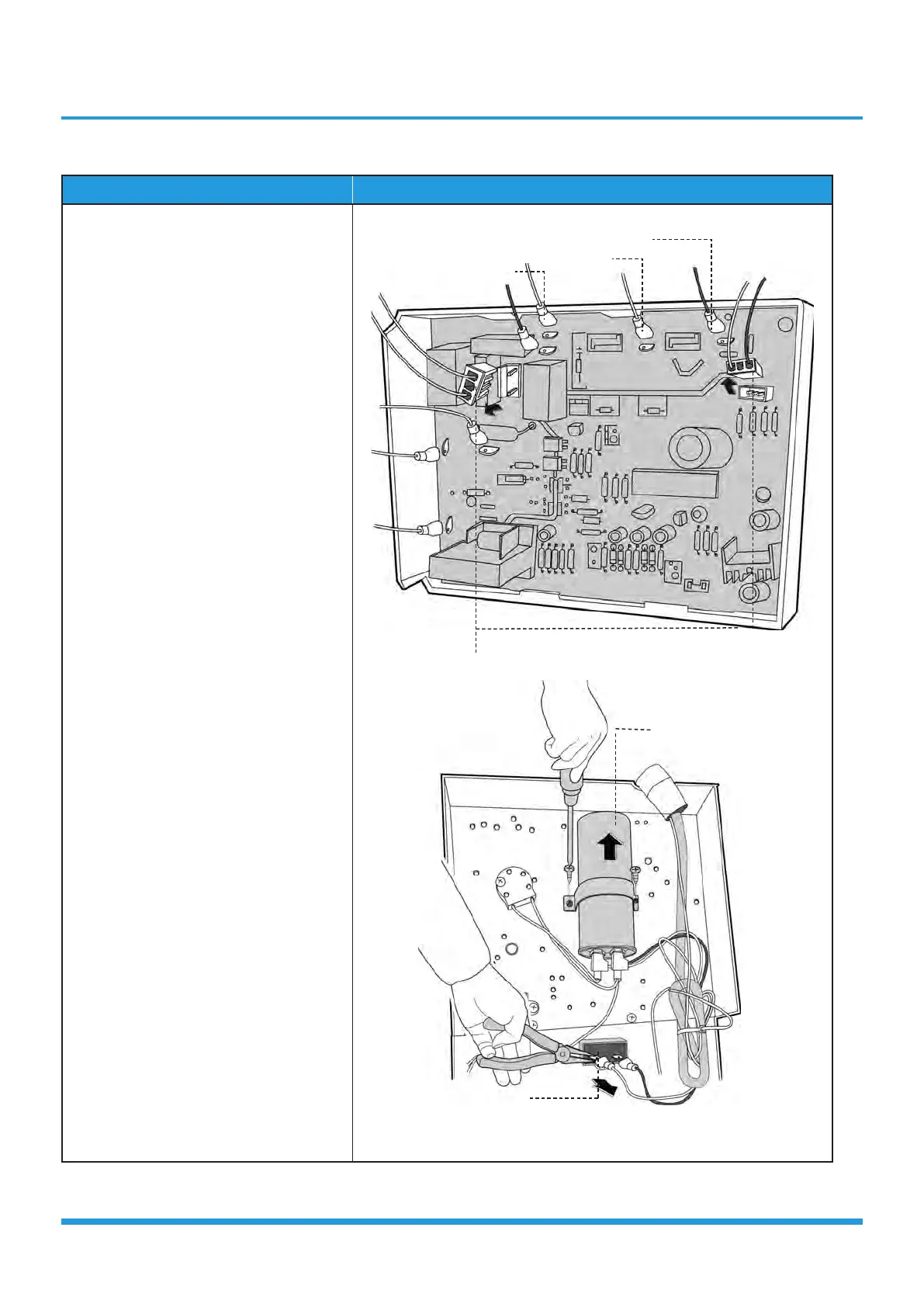
Procedure Illustration
1) Disconnect the wires connected to
the compressor. (Red wire connects
with PCB board, others connects with
terminals) (see CJ_ODU_PCB_002-1)
2) Disconnect the connectors for fan
motor. (Blue wire, red wire, brown
wire and black wire. The blue wire
and brown wire are on the capacitor.
The black wire connects with a
terminal. And the red wire is on the
borad.) (see CJ_ODU_PCB_002-1)
3) Disconnect the wires connected to
4-way valve. (see CJ_ODU_PCB_002-
1)
4) Disconnect the wires connected
to the transformer. (see CJ_ODU_
PCB_002-1)
5) Disconnect the other wires connected
to terminals. (see CJ_ODU_PCB_002-
1)
6) Remove the PCB board. (see CJ_
ODU_PCB_002-1)
7) Remove the screws of the capacitors.
(see CJ_ODU_PCB_002-2)
CJ_ODU_PCB_002-1
CJ_ODU_PCB_002-2
Note: This section is for reference only. Actual unit appearance may vary.
Fan Motor
4-Way Valve
Compressor
Transformer
Capacitor of compressor
Capacitor of Fan Motor
 Loading...