Outdoor Unit Disassembly 40
6. PCB board 7
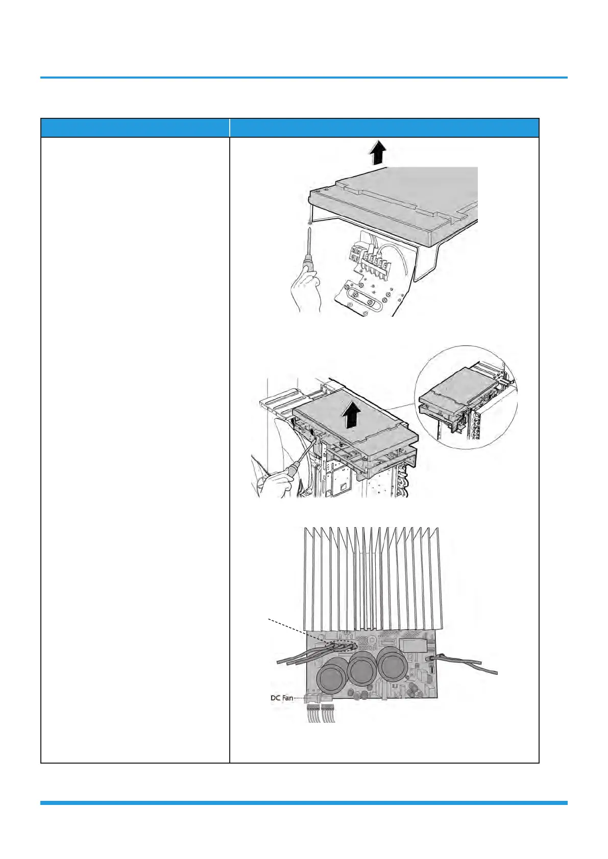
Procedure Illustration
1) Remove the screws of the top cover.
(1 screws) (see CJ_ODU_PCB_007-
1).
2) Unfix the hooks and then open the
electronic control box cover (5 hooks)
(see CJ_ODU_PCB_007-2).
3) Disconnect the connector for fan
motor from the IPM board (see CJ_
ODU_PCB_007-3).
4) Remove the connector for the
compressor (see CJ_ODU_PCB_007-
3).
CJ_ODU_PCB_007-1
CJ_ODU_PCB_007-2
CJ_ODU_PCB_007-3
Note: This section is for reference only. Actual unit appearance may vary.
Compressor
 Loading...