MCAC-VTSM-2015-10 R410A All DC Inverter V5 X Series 50Hz
Troubleshooting 143
4.9 xH0: Communication malfunction between main control chip and inverter driver chip
4.10 H1: Communication malfunction between main control chip and communication chip
The error will only display on faulty unit, all the ODUs will be on standby.
Note:
* How to check for transformer power supply
Check the voltage of 8(CN31), 9(CN33) and 24(CN35) terminals. The normal voltage of 8(CN31) and 9(CN33) terminals should
be 220V, the voltage between “GND” and “5V” of 24(CN35) terminal should be 5V, the voltage between “GND” and “12V of
24(CN35) terminal should be 12V. If the voltage is out of the range, the power supply for main PCB and transformer is abnormal.
* How to check for transformer
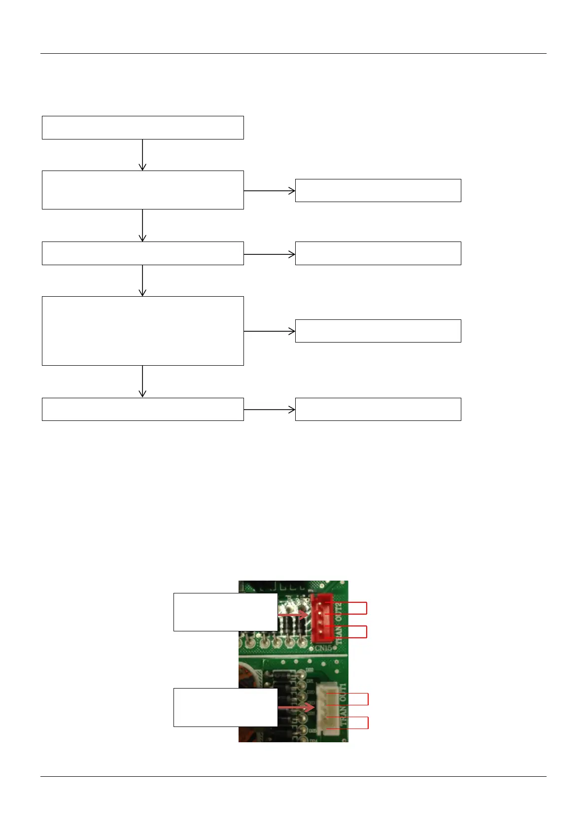
The voltage between upper tow pins of 18(CN32) terminal is AC 13.5V; the voltage between under tow pins of 18(CN32) terminal
is AC 9V. The voltage between upper tow pins of 19(CN34) terminal is AC 14.5V; the voltage between under tow pins of 19(CN34)
terminal is AC 14.5V
Outdoor main PCB is damaged
Replace the outdoor main PCB
Power supply for main PCB and
transformer is abnormal
*
The transformer is damaged
*
There is electromagnetic interference
near the unit, such as high-frequency
transmitter or other high strength
Provide normal power supply
CN34: Power output
of No.2 transformer
CN32: Power output
of No.2 transformer
 Loading...