MCAC-VTSM-2015-10 R410A All DC Inverter V5 X Series 50Hz
Installation 85
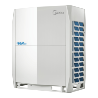
Illustration of screw bolt position
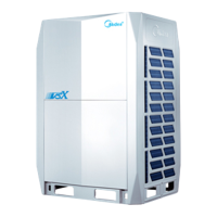
1.5 Master and slave unit setting
When the quantity of outdoor unit is more than two in one system, the outdoor unit should be set in order from
largest capacity unit to smallest capacity unit. The largest capacity unit must be placed on the first branch site,
and be set as master unit, while the others are set as slave units.
Take 44HP (composed by 10HP, 16HP and 18HP) as an example:
1) Place the 18HP on the first branch site.
2) Order the units from the largest capacity to smallest (See the detail placement illustration)
3) Set 18HP as the master unit, the 16HP and the 10HP as slave units.
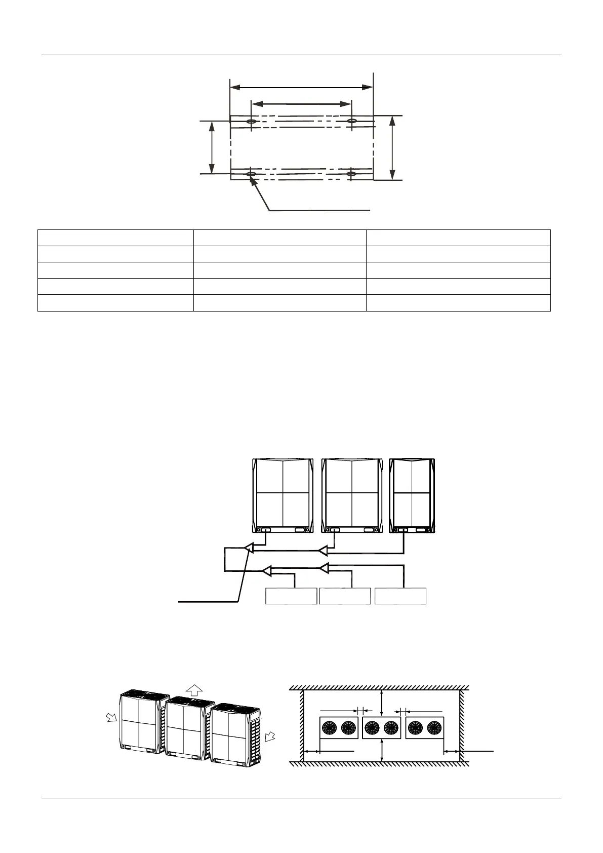
1.6 Installation space
Ensure enough space for maintenance. Modules combined in the same system must be on the same
height.
Unit: mm
15×23 long u-shape hole
B
A
C
D
The 1st branch joint
Outdoor unit
(44HP)
Indoor unit A Indoor unit B Indoor unit C
A(18HP) B(16HP)
C(10HP)
(Air-in )
(Air-in )
(Air-out )
Installation and maintenance surface
Top view of the outdoor unit
>1000mm
>1000mm
100mm~500mm
>1000mm
>1000mm
100mm~500mm
 Loading...