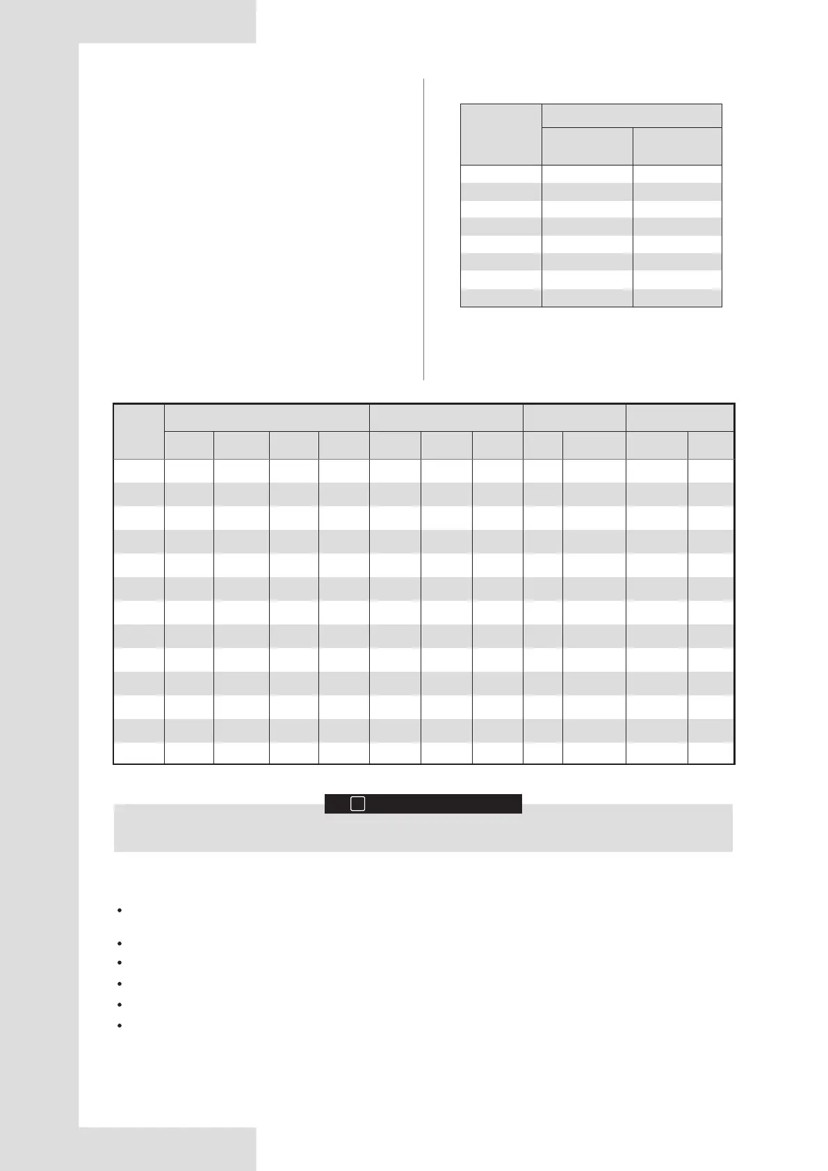
27
≤ 3
> 3 and ≤ 6
> 6 and ≤ 10
> 10 and ≤ 16
> 16 and ≤ 25
> 25 and ≤ 32
> 32 and ≤ 50
> 50 and ≤ 63
0.5 and 0.75
0.75 and 1
1 and 1.5
1.5 and 2.5
2.5 and 4
4 and 6
6 and 10
10 and 16
Table 4.13
Phase and frequency of power supply system: 3N-50Hz, Voltage: 380-415V
INFORMATION
i
4.4.1 Safety device requirements
4.4 Selecting and Preparing
the Electrical Wiring
1. Select the wire diameters (minimum value)
individually for each unit based on Table 4.13 and
Table 4.14, where the rated current in Table 4.13
refers to MCA in Table 4.14. If the MCA exceeds 63A,
the wire diameters should be selected according to
the national wiring regulation.
2. The maximum allowable voltage range variation
between phases is 2%.
3. Select circuit breakers that have a contact separation
in all poles not less than 3 mm providing full
disconnection, where MFA is used to select the
current circuit breakers and residual current operation
breakers:
1 to 2.5
1 to 2.5
1 to 2.5
1.5 to 4
2.5 to 6
4 to 10
6 to 16
10 to 25
Cable for fixed
wiring
Nominal cross-sectional area (mm
2
)
Flexible cords
Rated current
of appliance
(A)
Abbreviations:
MCA: Minimum Circuit Amps; TOCA: Total Over-current Amps; MFA: Maximum Fuse Amps; MSC: Maximum Starting
Current (A); RLA: Rated Load Amps; FLA: Fan Load Amps.
Units are suitable for use in electrical systems where voltage supplied to unit terminals is not below or above listed range
limits. The maximum allowable voltage variation between phases is 2%.
Select wire size based on the value of MCA.
TOCA indicates the total overcurrent amps value of each OC set.
MFA is used to select overcurrent circuit breakers and residual-current circuit breakers.
MSC indicates the maximum current on compressor start-up in amps.
RLA is based on the following conditions: indoor temperature 27°C DB, 19°C WB; outdoor temperature 35°C DB.
8HP
10HP
12HP
14HP
16HP
18HP
20HP
22HP
24HP
26HP
28HP
30HP
32HP
380-415
380-415
380-415
380-415
380-415
380-415
380-415
380-415
380-415
380-415
380-415
380-415
380-415
50
50
50
50
50
50
50
50
50
50
50
50
50
342
342
342
342
342
342
342
342
342
342
342
342
342
440
440
440
440
440
440
440
440
440
440
440
440
440
17.0
18.8
23.0
26.2
31.4
33.0
40.5
41.5
46.0
51.0
51.0
56.8
57.0
20.7
22.5
26.8
31.0
36.2
38.0
39.5
47.1
52.0
54.0
57.4
63.2
63.4
20
25
32
32
40
40
50
50
63
63
63
80
80
12.7
13.0
17.0
26.8
31.2
17.9+17.0
18.5+17.7
20.0+19.2
22.7+22.2
20.3+20.2
21.7+22.0
24.5+24.8
25.5+25.8
0.56
0.56
0.56
0.92
0.92
0.56+0.56
0.56+0.56
0.56+0.56
0.56+0.56
0.92+0.92
0.92+0.92
0.92+0.92
0.92+0.92
1.7
1.7
1.8
2.8
3.0
1.8+1.8
1.8+1.8
2.0+2.0
2.0+2.0
2.1+2.1
2.1+2.1
2.2+2.2
2.2+2.2
-
-
-
-
-
-
-
-
-
-
-
-
-
Table 4.14
Power Current Compressor Fan Motor
System
Outdoor Unit
Voltage
(V)
Min.
(V)
Max.
(V)
MCA
(A)
TOCA
(A)
MFA
(A)
MSC
(A)
RLA
(A)
Power
(kW)
FLA
(A)
Frequency
(Hz)