38
5.10 Electrical Wiring
5.10.1 Electrical wiring precautions
Take note of the risk of electrical shock
during installation.
All the electric wires and components must
be installed by installation personnel with the
proper electrician certification, and the
installation process must comply with
applicable regulations.
Use only wires with copper cores for the
connections.
A main switch or safety device that can
disconnect all polarities must be installed,
and the switching device can be completely
disconnected when the corresponding
excessive voltage situation arises.
Wiring must be carried out in strict
accordance with what is stated in the product
nameplate.
Do not squeeze or pull the unit connection,
and make sure the wiring is not in contact
with the sharp edges of the sheet metal.
Make sure the grounding connection is safe
and reliable. Do not connect the earth wire to
public pipes, telephone earth wires, surge
absorbers and other places that are not
designed for grounding. Improper grounding
may cause electrical shock.
Make sure the fuses and circuit breakers
installed meet the corresponding
specification requirements.
Make sure an electric leakage protection
device is installed to prevent electrical shock
or fires.
The model specifications and characteristics
(anti high-frequency noise characteristics) of
the electric leakage protection device are
compatible with the unit to prevent frequent
tripping.
Before powering on, make sure the
connections between the power cord and
terminals of the components are secure, and
the metallic cover of the electric control box is
closed tightly.
WARNING
8. When the amount charged reaches R (kg), close the
three valves. If the amount charged has not reached R
(kg) but no additional refrigerant can be charged,
close the three valves on the pressure gauge, run the
outdoor units in cooling mode, and then open the
yellow and blue valves. Continue charging until the full
R (kg) of refrigerant has been charged, then close the
yellow and blue valves. Note: Before running the
system, be sure to complete all the
pre-commissioning checks and be sure to open all
stop valves as running the system with the stop valves
closed would damage the compressor.
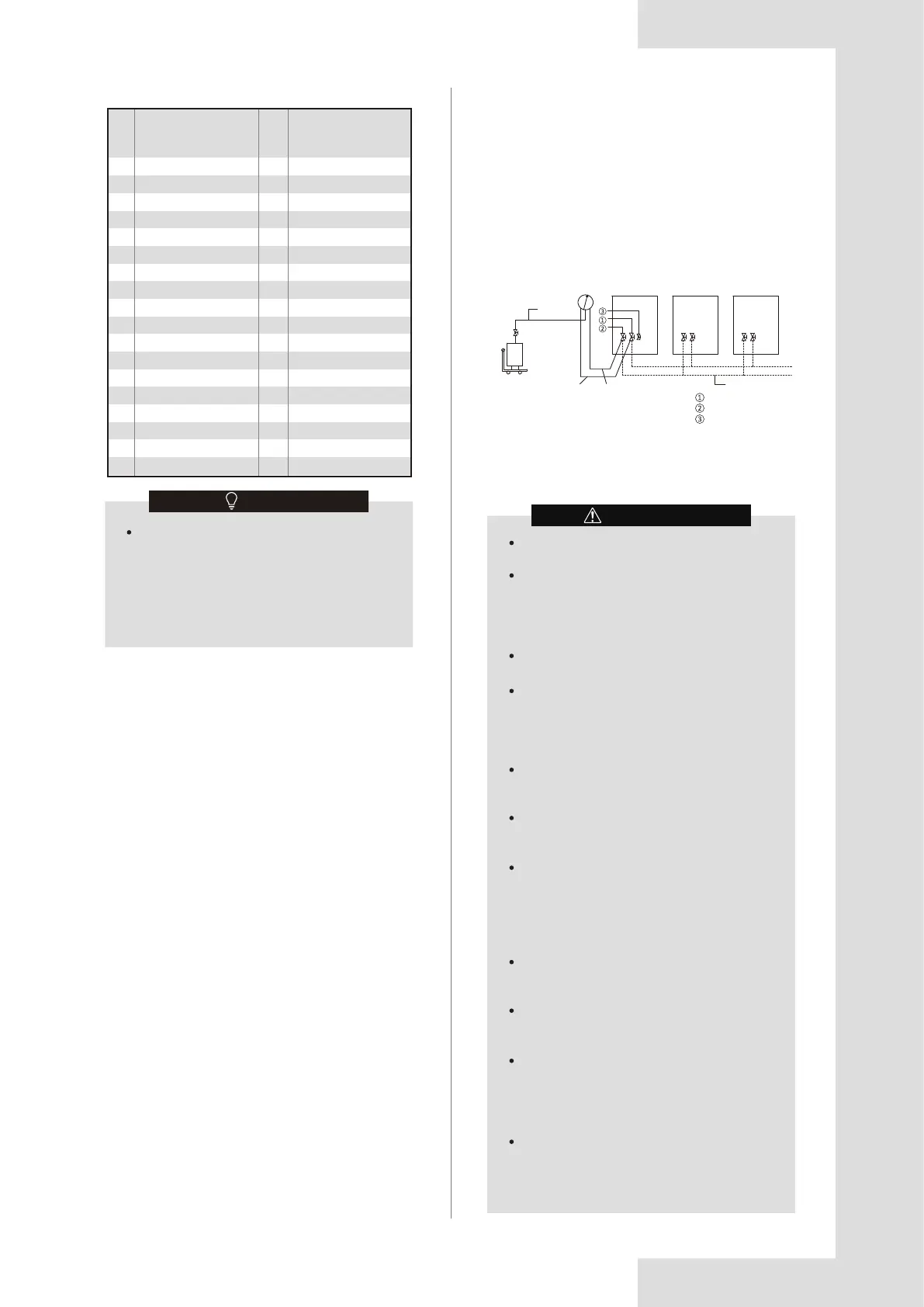
Figure 5.32
R410A
refrigerant tank
Weighing scale
Pressure gauge
Yellow hose
Blue hose
Red hose
Master unit Slave unit Slave unit
Field piping
Gas pipe stop valve
Liquid pipe stop valve
Service port
The refrigerant charge of the system must be
less than 100 kg. This means that in case the
calculated total refrigerant charge is equal to
or more than 100 kg you must divide your
multiple outdoor system into smaller
independent systems, each containing less
than 100 kg refrigerant charge. For factory
charge, refer to the unit name plate.
NOTE
The procedure for adding refrigerant is as follows:
1. Calculate additional refrigerant charge R (kg).
2. Place a tank of R410A refrigerant on a weighing scale.
Turn the tank upside down to ensure the refrigerant is
charged in a liquid state. (R410A is a blend of two
different chemical compounds. Charging gaseous
R410A into the system could mean that the refrigerant
charged is not of the correct composition).
3. After vacuum drying, the blue and red pressure gauge
hoses should still be connected to the pressure gauge
and the master unit stop valves.
4. Connect the yellow hose from the pressure gauge to
the R410A refrigerant tank.
5. Open the valve where the yellow hose meets the
pressure gauge, and open the refrigerant tank slightly
to let the refrigerant eliminate the air. Caution: open
the tank slowly to avoid freezing your hand.
6. Set the weighing scale to zero.
7. Open the three valves on the pressure gauge to begin
charging refrigerant.
Refrigerant charge amount of outdoor unit before
shipment (R0 kg)
The total refrigerant of the system (Rt) = refrigerant before
shipment (R0) + additional refrigerant in the field (R).
The
refrigerant charge of the system must be less than 100
kg. If the calculated total refrigerant charge is equal to or
more than 100 kg you must divide your multiple outdoor
system into smaller independent systems, each
containing less than 100 kg refrigerant charge.
For factory charge of outdoor unit, refer to the outdoor
unit name plate.
In case of a multi-outdoor-unit system,
calculate the total refrigerant charge before shipment of
the outdoor units to be combined.
Table 5.6
HP HP
Maximum additional
refrigerant charge
quantity (kg)
Maximum additional
refrigerant charge
quantity (kg)
28
30
32
34
36
38
40
42
44
46
48
50
52
54
56
58
60
62
69.3
69.6
69.9
70.2
70.5
70.8
71.1
71.4
71.6
72.0
72.3
72.5
72.8
73.1
73.4
73.7
74.0
74.3
64
66
68
70
72
74
76
78
80
82
84
86
88
90
92
94
96
74.6
74.9
92.7
93.1
93.4
93.7
93.9
94.2
94.6
94.8
95.1
95.4
95.7
96.0
96.2
114.2
114.4
Calculate the refrigerant charge of the system (Rt kg)