56
When maintaining and repairing the inverter:
1. Do not open the cover of the electrical component box
within 5 minutes after the power is switched off.
2. Verify that the power supply is switched off before you use
the measuring instrument to measure the voltage between
the main capacitor and the main terminal to ensure that the
capacitor voltage in the main circuit is less than 36 VDC. The
position of the main terminal has been shown in the Wiring
nameplate (The port of CN38 on the compressor drive
board).
3. Before you come in any contact with the circuit board or
components (including the terminals), make sure that static
electricity in your own body is eliminated. You can touch the
sheet metal of the outdoor unit to achieve this. If conditions
permit, please wear an anti-static bracelet.
4. During maintenance, pull out the plug connecting to the
power cord of the fan to prevent the fan from rotating when it
is windy outside. Strong winds will cause the fan to rotate
and generate electricity which can charge the capacitor or
terminals, leading to an electric shock. At the same time, do
take note of any mechanical damage. The blades of a fan
rotating at high speed are very dangerous and cannot be
operated by one person alone.
5. Once the maintenance is completed, remember to
reconnect the plug to the terminal; otherwise, a fault will
be reported for the main control board.
6. When the unit is power on, the fan of the unit with auto
snow-blowing function will run periodically, so make sure
the power supply is off before touching the unit.
Please refer to the wiring schematic on the back of the
box cover of the electrical component box for the
relevant details.
8.2.1 Prevent electrical hazards
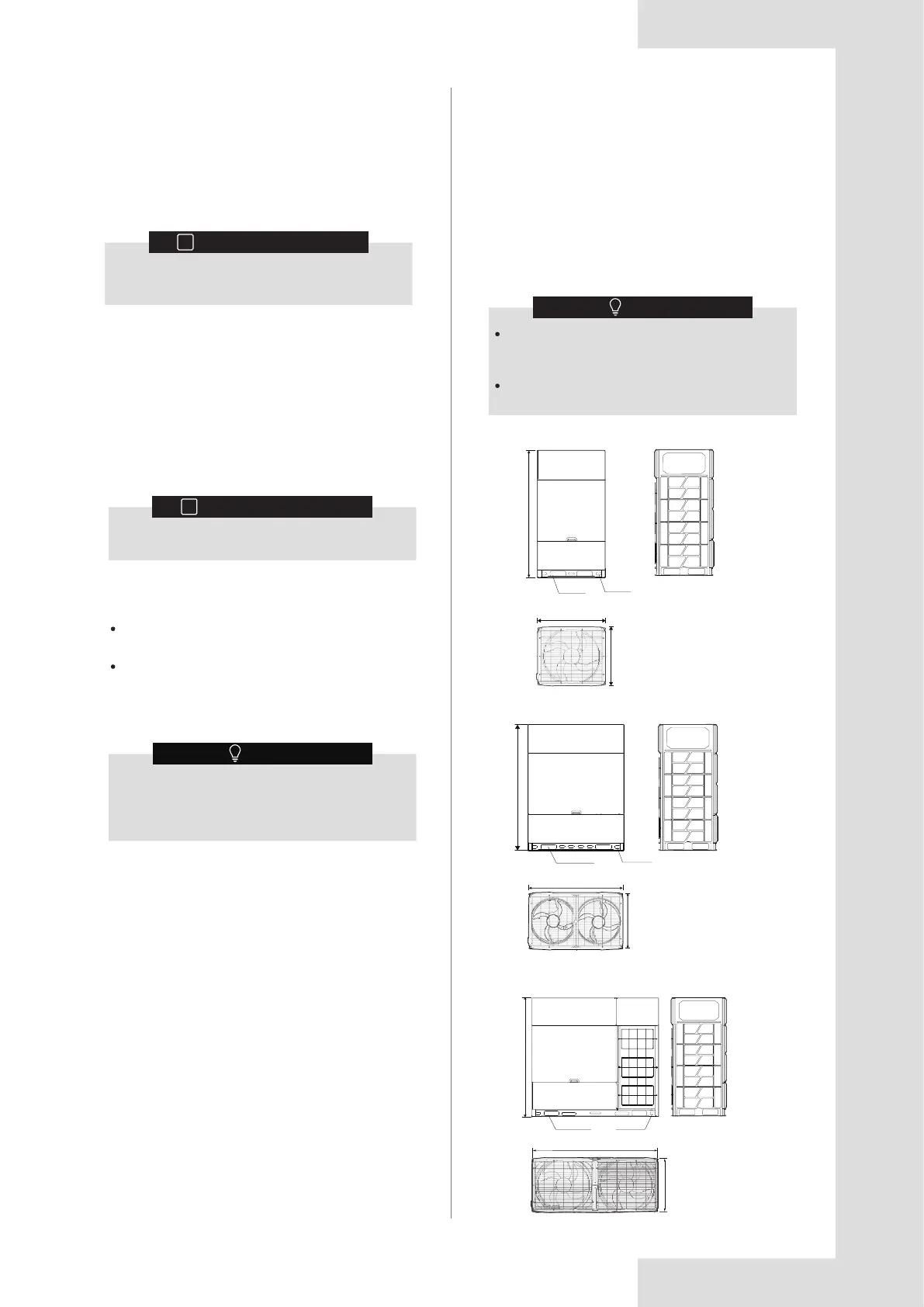
9 TECHNICAL DATA
8-16HP
Product dimensions may vary slightly due to
different panels and the tolerance is ±30mm. The
actual product shall prevail.
Product pictures in this manual are for reference
only.
NOTE
9.1 Dimensions
Figure 9.2
Figure 9.3
Figure 9.1
1760
220X70
70X40
940
825
1760
220X70
70X40
1340
825
1760
220X70
70X40
1880
825
Unit: mm
18-24HP
26-32HP
8.1 Overview
8.2 Safety Precautions for
Maintenance
8 MAINTENANCE AND REPAIR
INFORMATION
i
Arrange for the installation personnel or service
agent to carry out maintenance once every year.
Take electrical hazards preventive measures during
system maintenance and repair.
Recovery operation for refrigerant.
This chapter contains the following information:
7.7 Operating This Unit
Once the installation of this unit is completed, and the
test run of the outdoor and indoor units is done, you can
start to run the system.
The indoor unit user interface should be connected to
facilitate the operations of the indoor unit. Please refer to
the installation manual of the indoor unit for more details.
INFORMATION
i
Refer to the installation manual of the indoor unit
for details on other error codes related to the
indoor unit.
7.6 Rectifications after Test Run is
Completed with Exceptions
The test run is considered complete when there is no
error code on the user interface or the outdoor unit
display. When an error code is displayed, rectify the
operation based on the description in the error code
table. Try to conduct the test run again to check that the
exception has been corrected.
Before you carry out any maintenance or repair
work, touch the metal parts of the unit to
dissipate static electricity and protect the PCB.
NOTE