32
Make sure the refrigerant piping is installed in
accordance with applicable laws.
Make sure the piping and connections are
not placed under pressure.
After all the piping connections have been
completed, check to make sure there is no
gas leak. Use nitrogen to conduct the leak
check for gas.
NOTE
Note the precautions when connecting the
field piping for the refrigerant. Add brazing
material.
Use the attached piping fittings when working
on the pipeline engineering on site.
After installation, make sure the piping does
not come in contact with each other or the
chassis.
NOTE
5.4 Pipe Welding
5.4.1 Things to note when connecting the
refrigerant piping
5.4.4 Connecting refrigerant piping to
the outdoor unit
5.4.2 Connect refrigerant piping
During the test, do not exert a force greater
than the maximum allowed pressure on the
product (as shown on the nameplate).
Take appropriate precautions to prevent
refrigerant leakage. Ventilate the area
immediately if the refrigerant leaks. Possible
risks (An excessively high concentration of
refrigerant in an enclosed area can lead to
anoxia (oxygen deficiency); the refrigerant
gas may produce a toxic gas if it comes in
contact with an open flame.)
Refrigerant must be recovered. Do not
release it into the environment. Use
professional fluorine extraction equipment to
extract the refrigerant from the unit.
CAUTION
Connecting refrigerant piping to the outdoor unit
Connecting refrigerant piping to the indoor unit (refer
to the installation manual of the indoor unit)
Connecting the VRF piping assembly
Assembly for connecting refrigerant piping branch
joint
Bear in mind the following guidelines:
The fittings provided as accessories can be used to
complete the connection from the stop valve to the field
piping.
Before the refrigerant piping is connected, make sure
the indoor units and outdoor units are installed
properly. Refrigerant piping connection procedures
include:
× Incorrect
√ Correct
Braze
Stop valve is used correctly
▪
▪
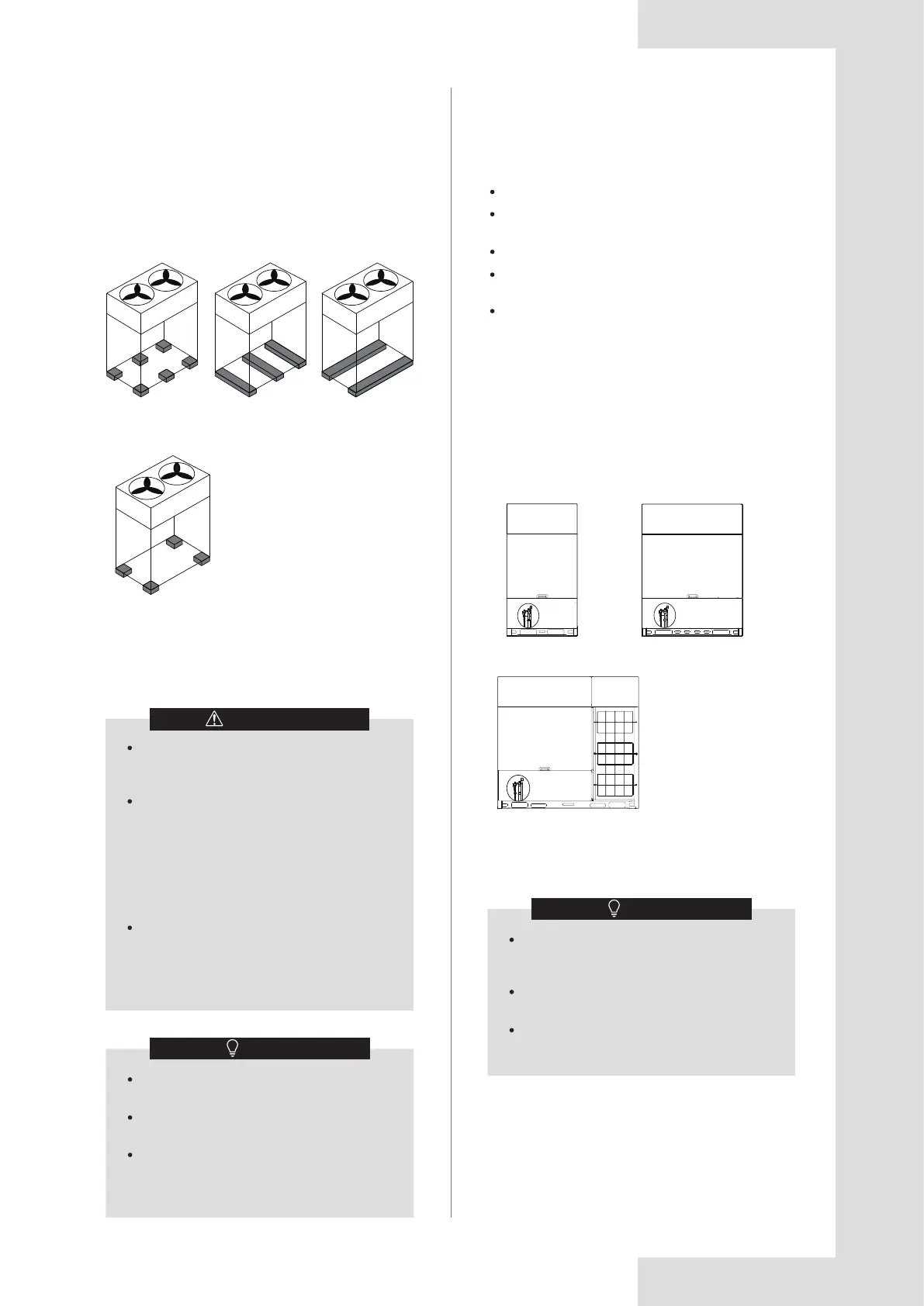
5.3.3 Vibration reduction of outdoor unit
The ODU shall be firmly fixed, and a thick rubber plate
or corrugated shock-absorbing rubber cushion with a
thickness of more than 20mm and a width of more than
100mm shall be placed between the unit and the
foundation. The shock-absorbing rubber cushion must
not be placed in a way that only supports the four
corners of the unit. The setting requirements are shown
in the figure below.
Figure 5.17
5.4.3 Outdoor refrigerant connecting pipe
position
The outdoor refrigerant connecting pipe position is
shown in the following figure.
8-16HP
18-24HP
26-32HP
Figure 5.16