30
Ensure there is enough space for maintenance.
The units in the same system must be placed at
the same height.
Outdoor units must be spaced so that sufficient
air may flow through each unit. Sufficient airflow
across heat exchangers is essential for outdoor
units to function properly.
NOTE
5.3 Installing the Outdoor Unit
5.3.1 Preparing the structure for installation
The base of the outdoor unit must use a solid
concrete surface such as cement or a steel beam
frame as a base.
The base must be completely level to ensure that
every point of contact is even.
During installation, make sure the base supports the
vertical folds of the front and back under plates of the
chassis directly as the vertical folds of the front and
back under plates are located where the actual
support for the unit load is.
No gravel layer is required when the base is built on
a roof surface, but the sand and cement on the
concrete surface must be level, and the base should
be chamfered along the edge.
A water drainage ditch should be set around the
base to drain water around the equipment. Potential
risk: slipping.
Check the load-bearing capacity of the roof to make
sure it can support the load.
When you choose to install the piping from the
bottom, the base height should be above 200mm.
Make sure the base where the unit is installed is
strong enough to prevent vibrations and noise.
200~300mm
40mm
Minimum
width 100mm
Drain size
100mmx20mm
Φ8 Expansion bolt
Depends on the positioning size of the unit
Figure 5.8
Figure 5.9
Use four ground bolts (M8) to
secure the unit in place. The
best option is to screw in the
ground bolt until it is embedded
in the base surface by at least 3
threads.
At least 3 threads
Please refer to the figure below for the installation
position of expansion bolts.
(14×22 U-shape hole)
B
A
C
D
Wooden frame
mounting hole
(outside)
Anchor bolt hole
(inside)
Size
HP
A B C D
U-shaped
hole
8-16HP 705 960 710 850
18-24HP 1105 1360 710 850
26-32HP 1645 1900 710 850
Φ14*22
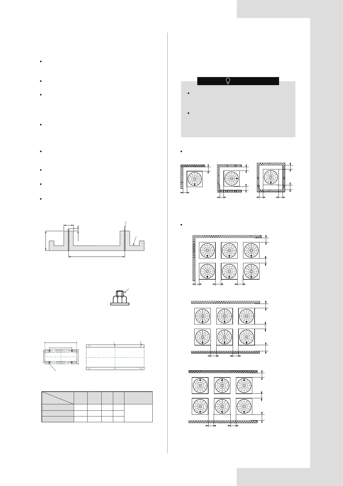
5.3.2 Outdoor unit installation space
Make sure there is sufficient space around the unit for
maintenance work, and the minimum space for air inlet
and air outlet is reserved (see below to select a feasible
method).
For single installation
Installation with walls in two directions
A
A
AA
A
A
A A A
Figure 5.11
Figure 5.12
A
A
AA
A
AA
A
A
B
B
BB
BB
Table 5.1
Figure 5.10
Unit: mm