29
The cover is clamped to the electric control box,
so be sure to remove it slowly during
disassembly.
NOTE
Make sure the power supply is off before you
carry out any electric control installation and
maintenance work.
To remove the entire electric control box, first
discharge the refrigerant from the system,
and disconnect the pipe connecting the
refrigerant radiator at the bottom of the
electric control box. At the same time,
remove all wiring connecting the electric
control box and the internal components of
the air conditioner.
The images shown here are for illustrative
purposes only and may differ from the actual
product due to model differences and product
upgrades. Please refer to the actual product.
CAUTION
18-32HP
Figure 5.5
To remove the entire electric control box,
discharge the refrigerant from the system
first, and then disconnect the pipe connecting
the refrigerant radiator at the bottom of the
electric control box, and remove all wiring
connecting the electric control box and the
internal components of the air conditioner.
The images shown here are for illustrative
purposes only and may differ from the actual
product due to model differences and product
upgrades. Please refer to the actual product.
WARNING
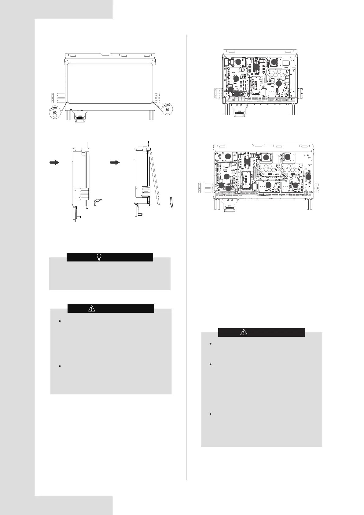
5.2.3 Internal components of electrical box
The heat radiator piping of the refrigerant is
connected to the system.
(1) Main control board
(2) Communication terminal block
(3) Terminal block
(4) AC filter board
(5) Compressor & Fan drive board A
(6) Compressor & Fan drive board B
(7) Reactance
(8) Reactance
(9) Cooling fan
(10) Cooling fan
8-16HP
18-32HP
Figure 5.6
Figure 5.7
2
3
1
4
10
5
7
1
4
5
6
7
8
10
9
3
2