Technical Information
83
DGC 6xxx
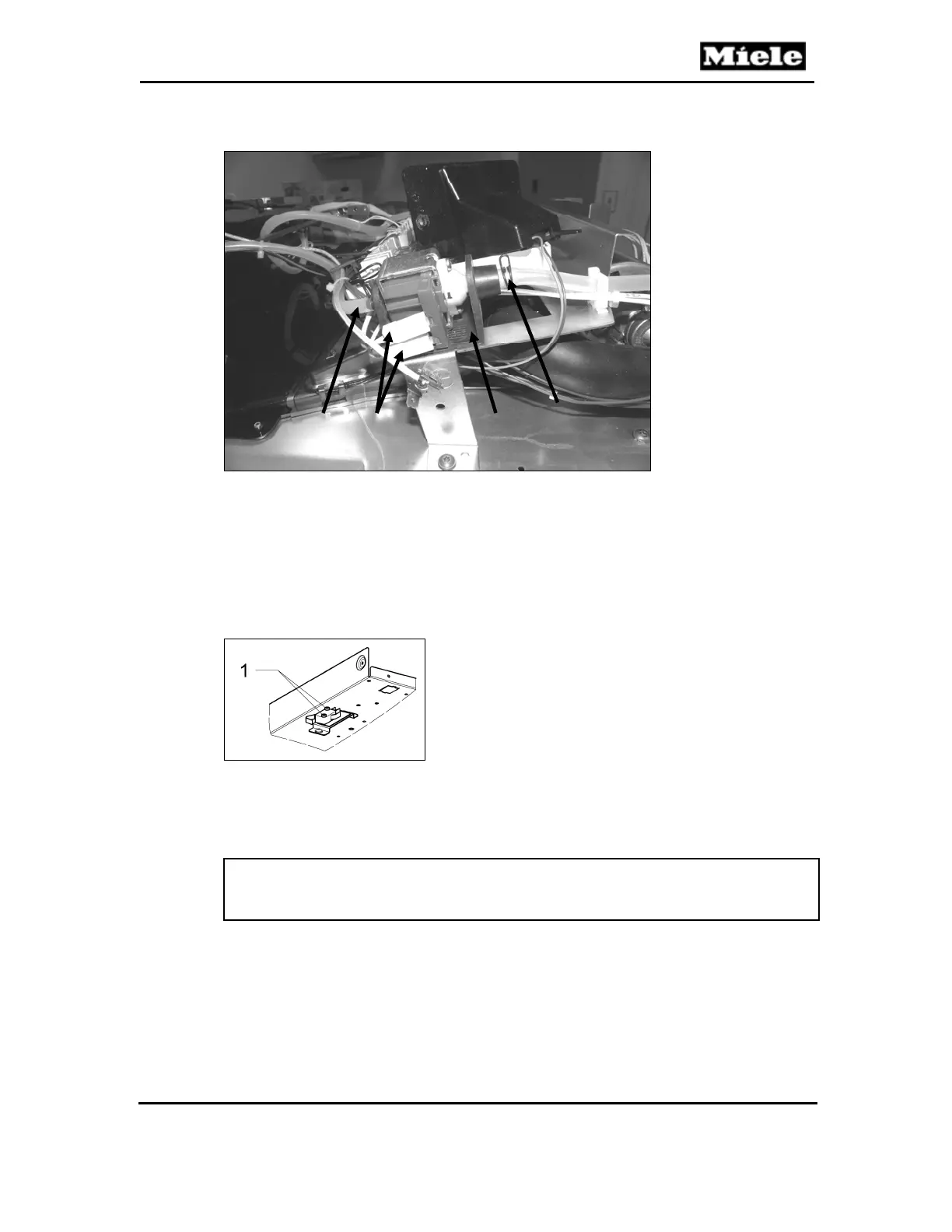
Figure 045-9: Feed Pump
4.4 Fascia Panel Position Switch (S60) Removal
1. Remove the appliance from its housing unit; see Section 010-4.1.
2. Disconnect the appliance from the power supply.
3. Remove the lid; see Section 010-4.2.
4. Remove the two Phillips screws securing the position switch (Figure 045-
10, Item 1).
Figure 045-10: Position Switch Screws
5. Disconnect the electrical connections from the switch.
4.5 Water Container Switch (B3-17, B3-18, B3-19) Removal
Note:
The water tank switches (B3-17 and B3-18) are part of one assembly and
must be replaced together.
1. Remove the appliance from its housing unit; see Section 010-4.1.
2. Disconnect the appliance from the power supply.
3. Remove the lid; see Section 010-4.2.
4. Unclip the appropriate switch(es) from the water container; see Figure
045-11, Item 1.
5. Disconnect the switch(es) from the power electronic.
1 2
2
3
 Loading...