7
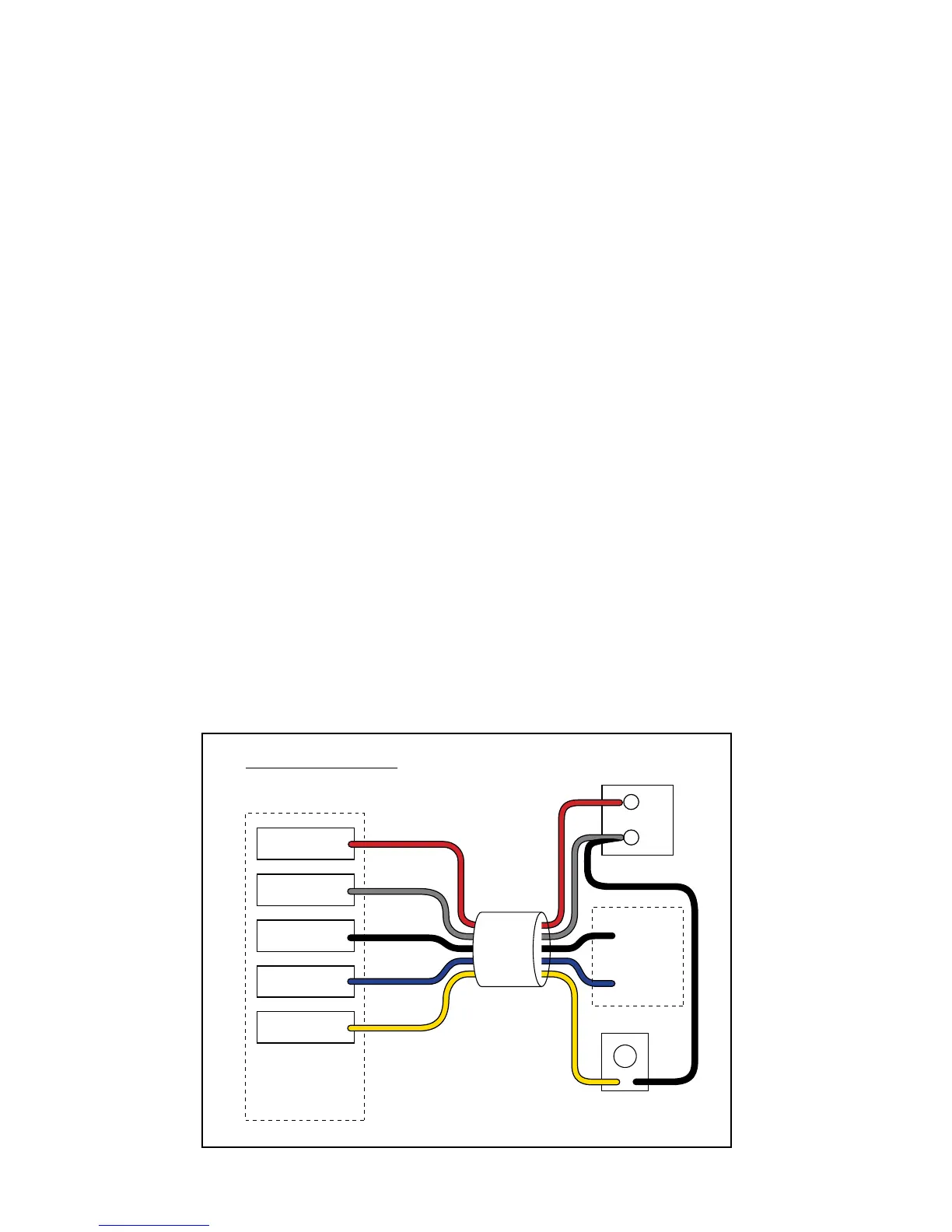
Typical Gate Wiring Connection:
• Reference Leads:
o RED => Input Voltage (+)
o SHIELD => Ground/Common (–)
o BLACK => Relay’s Common
o BLUE => Relay’s Normally Open
o YELLOW => Remote SENSOR [Range adjustment potentiometer (POT)]
• Terminology Definitions:
o ‘FREE EXIT/ENTRY’ is defined as input terminals (2) that upon activation (momentarily connected together) will
cause the gate to run in the open direction only. Note: In most gate openers, one of the two terminals is the ‘COM-
MON/GND’.
• Power supply connection:
o DC power supply: (11-36 Vdc)
ß Connect the positive (+) lead of the power supply to the RED wire.
ß Connect the negative (-) lead of the power supply to the SHIELD wire.
o AC power supply: (8-26 Vac)
ß Connect the power supply to the RED & SHIELD wires. There is no polarity for AC power supply.
• Relay output connection:
o Connect the BLUE wire from the SENSOR to the ‘FREE EXIT/ENTRY’ of the gate opener.
o Connect the BLACK wire from the SENSOR to the ‘COMMON/GND’ of the gate opener.
• Range (POT) board connection:
o Connect the YELLOW wire from the SENSOR to the YELLOW wire from the Range Adjustment Board.
o Connect the BLACK wire from the Range Adjustment Board to a negative input voltage.
o Turn the POT clockwise to increase range.
o Turn the POT counter-clockwise to decrease range.
For Installation on Other Brand Gate Openers ...
If you are using the VEHICLE SENSOR on any other automatic gate opener brand, use the informa-
tion below for wiring the system. If you do not understand the instructions below, please call GTO’s
Technical Support at 1-800-543-1236.
Input
Voltage (+)
Input
Voltage (–)
Relay Output
Common
Relay Output
Normally Open
Range
Adjustment
Range
Adjustment
Board
Input Voltage
11 - 36 Vdc or
8 - 26 Vac
–
+
Free Exit/Entry
Connections
SENSOR
RED
SHIELD
BLACK
BLACK
BLUE
YELLOW
YELLOW
Generic Wiring Diagram