5
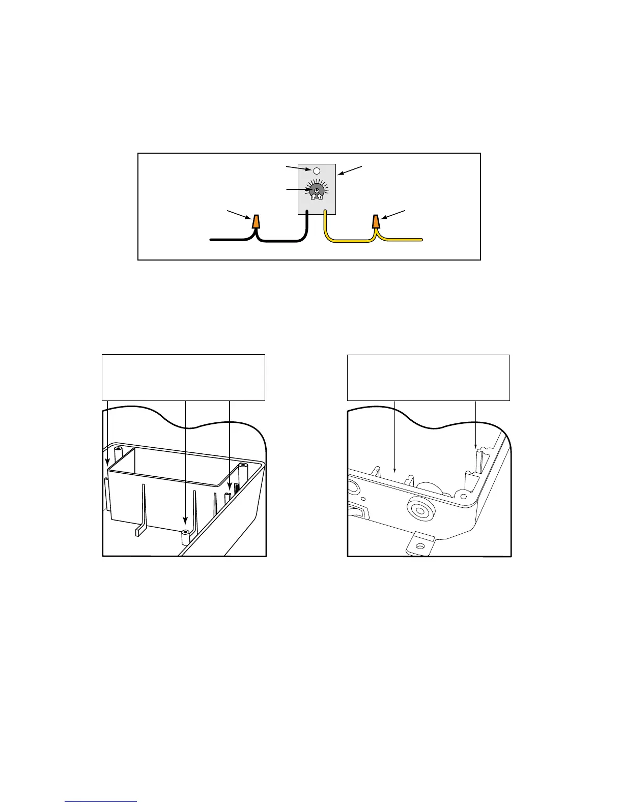
Connecting the Range Adjustment Control Board:
Step 9: Connect the YELLOW wire from the SENSOR CABLE to the YELLOW wire from the Range Adjustment
control board using one of the WIRE NUTS provided.
Step 10: Connect the BLACK wire from the Range Adjustment control board to the BLACK BATTERY
CONNECTOR wire (provided), along with the SHIELD wire from the SENSOR CABLE (see Step 13 below).
Step 11: Secure the RANGE ADJUSTMENT CONTROL BOARD inside the gate opener control box. The
control box has slots on both sides of the top battery compartment for extra control boards, or you can use the
optional mounting hole.
IMPORTANT: DO NOT let exposed wiring or components on the control board make contact with other exposed
wiring or components.
Potentiometer (POT)
Range Adjustment
Control Board
Wire NutWire Nut
Optional Mounting Hole
YELLOW wire
from SENSOR Cable
YELLOW
BLACK
BLACK BATTERY
CONNECTOR wire provided
MIN MAX
Power supply connection:
Step 12: Connect the RED and BLACK control board wires from the opener to the DOUBLE SPADE
CONNECTORS (provided) as shown on the next page.
Step 13: Using a WIRE NUT, connect the SHIELD wire from the SENSOR CABLE (along with the BLACK
wire from the Range Adjustment board) to the BLACK BATTERY CONNECTION wire provided. Using the
remaining WIRE NUT connect the RED wire from the SENSOR CABLE to the RED BATTERY CONNECTION
wire provided.
Step 14: Connect these wires to the DOUBLE SPADE CONNECTORS as shown.
IMPORTANT: Be sure to connect both RED leads to the same DOUBLE SPADE CONNECTOR and both
BLACK leads to the other DOUBLE SPADE CONNECTOR. You will connect the DOUBLE SPADE
CONNECTORS to the battery in the next step.
The Range Adjustment Control Board
can be mounted in slots on either side of
top battery compartment OR the mount-
ing hole beneath battery compartment.
Mighty Mule FM500 & FM502 Control Box
The Range Adjustment Control Board
can be mounted in the slot at the bottom
OR the slot at the bottom right. Both are
located beneath the circuit board.
Mighty Mule FM700 & FM702 Control Box