26
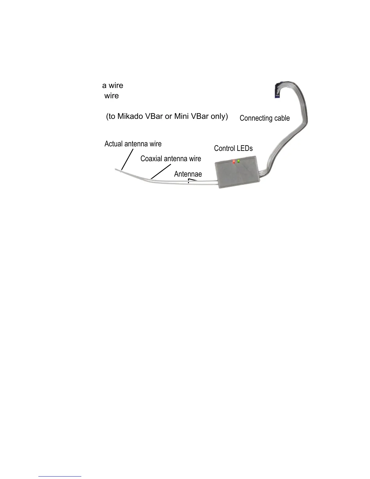
Antennae
Coaxial antenna wire
Connecting cable
Control LEDs
Actual antenna wire
VBar Control Satellite Receiver
Features
■ Antennae
» Coaxial antenna wire
» Actual antenna wire
■ Connector
■ Connecting cable (to Mikado VBar or Mini VBar only)
■ Control LEDs
Control LEDs
■ The green LED signals the receiver is bound to and synced with VBar Control.
■ The red LED ashes when data are being sent, e. g. telemetry is active.
VBar Control Receiver installation
■ Place the receiver next to the VBar Flybarless controller.
■ Fix it using e. g. double sided adhesive tape or velcro tape. Make sure it does not touch
the frames/chassis directly to avoid vibration inuence.
■ Avoid places where liquids could spill the receiver, take waterproong measures if need
be.
■ Avoid places where high temperature changes can occur.
■ Take measures so wires or antennae do not get damaged e. g. by sharp-edged carbon
ber or aluminum frames.
■ Make sure the connector is securely attached and the wire is not subject to tension or
kinking.
Placement of antennae in the model
■ Place the antennae in a way so the actual antennae do not touch frames or chassis ele-
ments and have free space around the tip by the size of a table tennis ball.
■ In case the actual antennae touch conductive or shielding material such as metal or
carbon ber surfaces, the reception will be reduced considerably.
■ Align the antennae in a way so they point at a 90° angle.