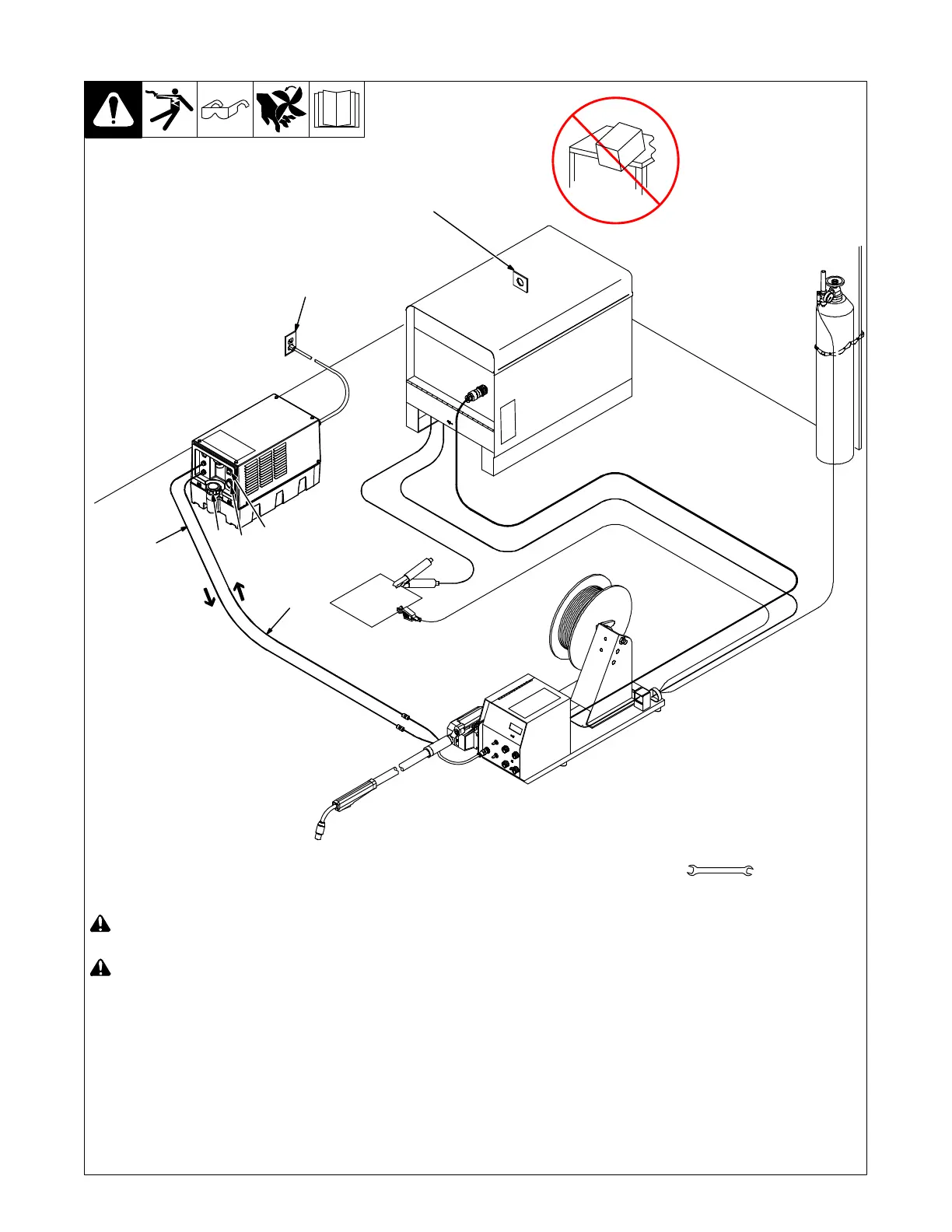
. A complete Parts List is available at www.MillerWelds.com
OM-628 Page 9
5-2. GMAW Connections
Ref. 801191-E
Tools Needed:
5/8 in.
! Do not move or operate unit where
it could tip.
! 230 volt AC coolers only: Replace
power cord plug if supplied plug
does not match receptacle. Have a
qualified person install correct 230
volt AC plug according to national
and local codes.
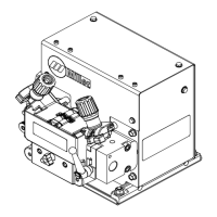
1 Lift -Eye
If placing cooling unit on welding power
source, slots are provided in bottom of unit
so it fits over lift-eye.
To prevent overheating, make sure cooling
unit is positioned so airflow is not restricted.
2 115 Or 230 Volt AC Grounded Re-
ceptacle (Depending On Model)
An individual circuit capable of carrying 15
amperes and protected by fuses or circuit
breakers is recommended. Recom-
mended fuse or circuit breaker size is 15
amperes. For 230 volt models, an individu-
al branch circuit capable of carrying 10 am-
peres and protected by fuses or circuit
breakers is recommended. Recom-
mended fuse or circuit breaker size is 10
amperes.
NOTICE − If welding power source has a
water valve, do not connect hoses to water
valve. Connect hoses as shown.
3 Coolant Out Hose
4 Coolant In Hose
Fittings have 5/8-18 left-hand threads.
Connect hoses with proper fittings as
shown.
5 Coolant Tank Cap
Use table in Section 4-3 to select proper
coolant, and fill tank. Maintain coolant level
at approximately 1 in. (25 mm) below top of
filler neck.
6 Flow Indicator
7 Power Switch
Operation:
Turn power switch On. Flow indicator spins
to indicate that at least 0.53 qt/min (0.5
L/min) of coolant is flowing.
3
4
5
1
2
7
6





 To Next Page