A
autumnmyersJul 27, 2025
What to do if I have bad weld connections on my Miller Welding System?
- LLaura MunozJul 27, 2025
If you are experiencing issues with weld connections, you can clean them or tighten weld cable connections.
What to do if I have bad weld connections on my Miller Welding System?
If you are experiencing issues with weld connections, you can clean them or tighten weld cable connections.
What to do with weld terminals on Miller Continuum?
To fix issues with weld terminals, you can clean or change them.
What to do if I see cracked parts on my Miller Continuum?
If you find cracked parts, you can check or replace them.
What to do if I have a damaged gas hose on my Miller Welding System?
If you have a damaged gas hose, you can replace it.
What to do if I have unreadable labels on my Miller Continuum Welding System?
If the labels are unreadable, you can change or replace them.
Explains the meaning of various safety symbols used throughout the manual to indicate hazards.
Details the primary hazards associated with arc welding processes and necessary precautions.
Provides additional safety symbols and explanations relevant to the installation, operation, and maintenance of the equipment.
Lists chemical warnings mandated by California Proposition 65 regarding potential health risks.
References key industry standards and organizations for welding safety and practices.
Explains electromagnetic fields (EMF) generated by welding and their potential impact on medical implants.
Illustrates and defines additional safety symbols found on CE products, with their associated warnings.
Presents a glossary of miscellaneous symbols used in the manual, covering various operational parameters and functions.
Indicates where to find the serial number and rating information for the product.
Details the technical specifications of the wire feeder, including input power, dimensions, and weight.
Outlines the IP rating and temperature ranges for operating and storing the equipment.
Provides a table correlating wire types and sizes with recommended wire feed speeds for different processes.
Guides the user on selecting an appropriate location for the power source and wire feeder, considering airflow and movement.
Details considerations for positioning the wire feeder, including the use of lifting eyes.
Provides dimensions and specifications for mounting holes, indicating the correct bolt size for installation.
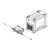
Illustrates the complete connection diagram for the power source, wire feeder, gas cylinder, and workpiece.
Explains the procedure for correctly connecting the weld output cable, emphasizing proper torque and cleanliness.
Details the pinout and socket information for the RC2 remote control receptacle on the wire feeder.
Describes how to connect the control cable between the welding power source and the wire feeder.
Identifies the gun trigger receptacles on the lower front panel of the wire feeder.
Instructs on connecting the shielding gas hose to the fitting on the rear of the wire feeder.
Explains the function of the Jog/Retract switch for feeding or retracting wire, and the associated symbols.
Details how to adjust the drive assembly angle for optimal wire feeding and gun cable management.
Provides instructions for installing welding guns, both with and without Accu-Mate connections.
Guides the user through the process of installing wire guides and drive rolls for proper wire feeding.
Covers the installation of wire spools, drive rolls, and the procedure for threading welding wire through the feeder.
Presents a diagram of the wire feeder's front panel user interface, identifying all controls and displays.
Provides a detailed explanation of each control, button, and indicator on the wire feeder's front panel.
Describes the controls located on the lower front panel of the wire feeder, including jog and trigger functions.
Illustrates the default LCD home screen, showing the directory path, program information, and navigation soft keys.
Details the Setup Menu, allowing users to create, modify, and manage weld programs and configurations.
Explains the Logs Menu, providing access to error logs and boot logs for system diagnostics.
Describes the Status Menu, which displays system status, load bank modes, and Accu-Power mode information.
Outlines the step-by-step process for creating, modifying, and saving weld programs on the wire feeder.
Explains how to configure trigger functions such as dual schedule, 4T, and trigger hold for various welding processes.
Details how to configure weld sequence parameters like preflow, start, crater, and postflow for optimized welding.
Describes how to set up voltage feedback methods, choosing between Stud Sense and Sense Lead.
Covers the System Menu options, including factory reset, USB functions, software revision, and network settings.
Explains the procedure for performing a factory reset to restore default settings on the wire feeder.
Details how to use USB functions for software updates, program loading/saving, and accessing system settings.
Outlines the recommended routine maintenance schedule for the wire feeder, including checks, changes, and replacements.
Provides a guide to interpreting LED and LCD error messages and offers solutions for troubleshooting faults.
Lists common troubleshooting issues for wire feeding and motor operation, with suggested remedies.
| Brand | Miller |
|---|---|
| Model | Continuum |
| Category | Welding System |
| Language | English |