OM-266409 Page 20
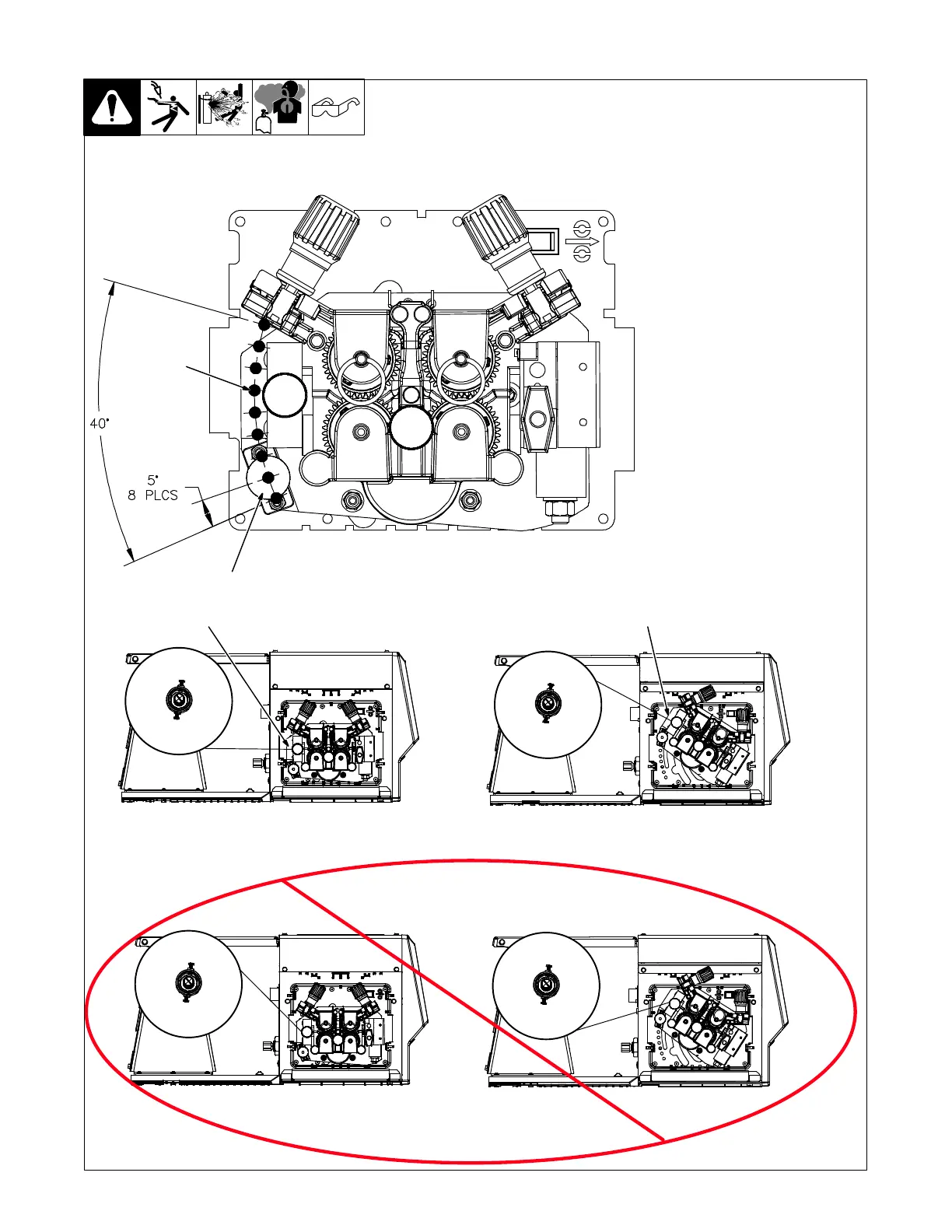
5-11. Rotating Drive Assembly
Ref. 259 144-A / 269 820-A
3
1 Retaining Knob And Pin
2 Adjustment Holes (8)
Each hole location is spaced at 5
degree increments. There are a to-
tal of eight holes for a range of 40
degrees. The second hole from the
bottom positions the wire drive as-
sembly parallel with the feeder
base.
To rotate the drive assembly, pull
retaining knob out and hold it while
rotating drive assembly. Release
knob at desired position to lock
drive assembly in place.
3 Wire Angle at Drive Assembly
Rotate the drive assembly to re-
duce bends in the mig gun cable.
Wire can be setup to feed off either
the top or bottom of wire spool. Se-
lect the option that results in the
straightest possible path into drive
assembly.
2
1
Wire Feeds Off Bottom Of Spool
Wire Feeds Off Top Of Spool
3
Good
Bad