OM-266409 Page 11
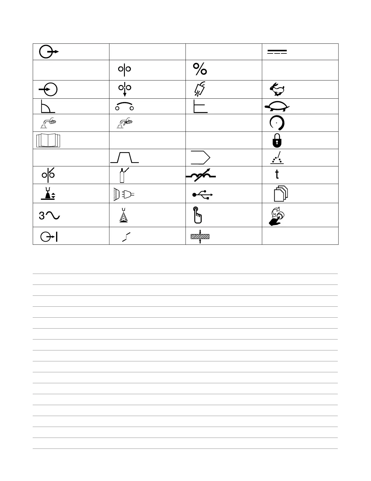
3-2. Miscellaneous Symbols And Definitions
.
Some symbols are found only on CE products.
Output
A
Amperes
V
Volts
Direct Current
(DC)
Duty Cycle Wire Feed Percent
Degree Of
Protection
Input
Cold Jog (Inch)
Towards
Workpiece
Purge By Gas Fast
Constant Current Circuit Breaker Constant Voltage Slow
Trigger Hold Off Trigger Hold On
I
2
Rated Welding
Current
Increase
Read Instructions
U
1
Primary Voltage
U
2
Conventional Load
Voltage
Locked
I
1
Primary Current Sequence Program Process
Wire Type Gas Type
Variable
Inductance
Time
Arc Length Line Connection USB Memory
Three Phase Arc Control Push Button
Rotating Knob And
Push Button
Output On
Synergic Mode
Active
Material Thickness