EasyManua.ls Logo

Miller GA-17C - Section 3 - Installation; Gun;Wire Feeder Connections

Miller GA-17C
12 pages
Print Icon
To Next Page IconTo Next Page
To Previous Page IconTo Previous Page
Loading...
SECTION
3-
INSTALLATION
Contact
Tube
Nozzle
Contact
Tube
Adapter
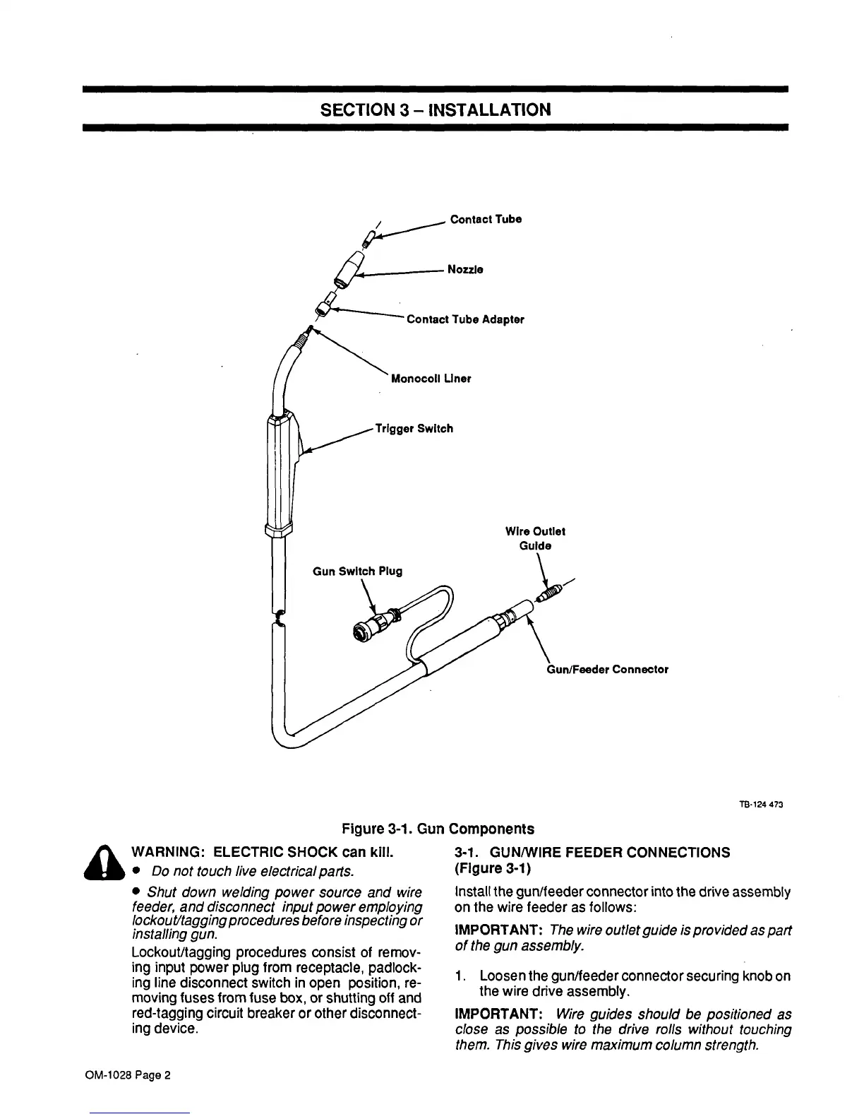
Figure
3-1.
Gun
Components
Connector
TB.124
473
a
WARNING:
ELECTRIC
SHOCK
can
kill.
Do
not
touch
ilve
electrical
parts.
Shut
down
welding
power
source
and
wire
feeder,
and
disconnect
input
power
employing
locko
uttagging
procedures
before
inspecting
or
installing
gun.
Lockout/tagging
procedures
consist
of
remov
ing
input
power
plug
from
receptacle,
padlock
ing
line
disconnect
switch
in
open
position,
re
moving
fuses
from
fuse
box,
or
shutting
off
and
red-tagging
circuit
breaker
or
other
disconnect
ing
device.
3-1.
GUN/WIRE
FEEDER
CONNECTIONS
(Figure
3-1)
Install
the
gun/feeder
connector
into
the
drive
assembly
on
the
wire
feeder
as
follows:
IMPORTANT:
The
wire
outlet
guide
is
pro
vided
as
part
of
the
gun
assembly.
1.
Loosen
the
gun/feeder
connector
securing
knob
on
the
wire
drive
assembly.
IMPORTANT:
Wire
guides
should
be
positioned
as
close
as
possible
to
the
drive
rolls
without
touching
them.
This
gives
wire
maximum
column
strength.
Monocoll
Liner
Trigger
Switch
Gun
Switch
Plug
Wire
Outlet
Guide
OM-1028
Page
2