EasyManua.ls Logo

Miller OM-257 675D User Manual

Miller OM-257 675D
164 pages
To Next Page IconTo Next Page
Page #1 background imageLoading...
Page #1 background image
OM-257 675D 201403
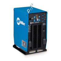
Auto-Axcess E Digital
Welding Power
Sources
Processes
Description
MIG (GMAW) Welding
Pulsed MIG (GMAW-P)
Flux Cored (FCAW) Welding
Automatic Welding
Automatic Welding Interface And
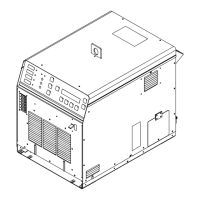
Arc Welding Power Source
File: Advanced Manufacturing Systems
Visit our website at
www.MillerWelds.com/ams
Scan this tag with your mobile device
to learn more about this product.
Individual carrier rates may apply.
Start by downloading the free
mobile app at http://gettag.mobi

Table of Contents

Questions and Answers:

Miller OM-257 675D Specifications

General IconGeneral
BrandMiller
ModelOM-257 675D
CategoryWelding System
LanguageEnglish

Summary

Section 1: Safety Precautions - Read Before Using

Arc Welding Hazards

Details hazards like electric shock, hot parts, and general safety precautions.

General Welding Safety

General Welding Safety

Covers hazards from fumes, gases, arc rays, fire, explosion, and flying metal/dirt.

Electromagnetic Interference Hazards

California Proposition 65 Warnings and EMF Information

Section 2: Safety Precautions - Read Before Use

Hazards Related to Arc Welding

Covers hazards like electric shock, hot parts, fumes, gases, and fire/explosion risks.

Specific Hazard Warnings

Specific Hazard Warnings

Covers eye injury, gas accumulation, EMF, and noise hazards, plus cylinder safety.

Additional Hazards for Installation, Operation, and Maintenance

Additional Hazards for Installation, Operation, and Maintenance

Covers additional hazards like fire, explosion, falling equipment, and overheating.

Equipment Handling Hazards

Equipment Handling Hazards

Covers ESD, moving parts, wire hazards, and battery explosion risks.

Section 2: Safety Precautions - Read Before Use

Section 4: Specifications for Auto-Axcess E 300 Digital

Duty Cycle and Overheating

Duty Cycle and Overheating

Explains duty cycle percentage and overheating protection measures.

Electrical and Environmental Specifications

Electrical Service Guide

Provides recommendations for electrical service, fuse ratings, and conductor sizes.

Section 5: Specifications for Auto-Axcess E 450 Digital

Section 6: Specifications for Auto-Axcess E 675 Digital

Unit Specifications

Lists detailed specifications including input power, output, voltage, and wire feed ranges.

Section 8: General Installation

Connection Diagrams and Receptacles

Connection Diagram

Illustrates the typical connections between the welding power source, robot, and other components.

Rear Panel Receptacles and Functions

Peripheral and Touch Sensor Operations

Motor Control Receptacle and Capacitor Voltage Measurement

Input Capacitor Voltage Measurement

Measuring Input Capacitor Voltage

Provides a procedure for safely measuring input capacitor voltage.

Connecting 3-Phase Input Power

Connecting 3-Phase Input Power

Illustrates the connection procedure for 3-phase input power to the unit.

Connecting 3-Phase Input Power (Continued)

Continues the explanation of 3-phase input power connection, including safety and conductor selection.

Section 9: Recommended Setup Procedures

Connecting To Weld Terminals

Details the correct procedure for connecting cables to the weld output terminals.

Cable Selection and Process Considerations

Selecting Weld Cable Sizes*

Provides a chart and guidelines for selecting appropriate weld cable sizes based on length and amperage.

Welding Circuit and Cable Arrangement

Welding Circuit

Explains welding circuit loop minimization and voltage sensing lead connection.

Arranging Welding Cables To Reduce Welding Circuit Inductance

Demonstrates methods for arranging cables to minimize inductance.

Multiple Power Sources and Arc Blow

Voltage Sensing Lead and Work Cable Connections

Voltage Sensing Lead and Work Cable Connections for Multiple Welding Arcs (Bad Setup)

Illustrates bad setups for voltage sensing and work cable connections.

Earth Grounding and MIG Welding Mechanics

Earth Grounding

Explains the importance of earth grounding and how to check resistance.

Robot Signals and ADAM-6050 Setup

ADAM-6050 Program Loading and Configuration

ADAM-6050 Configuration and Robot Control

Weld Cycle Timing, Touch Sensor, Stick Check, and Arc Blow

Touch Sensor Operation

Explains how the touch sensor feature works for locating weldments.

Basic Welding Troubleshooting

Basic Welding Troubleshooting

Continues troubleshooting startup issues, communication errors, and gas flow problems.

Electrical Functions of Automated Welding Systems

Section 10: Operation

Operational Terms and Pulse Welding

Front Panel Controls

Front Panel Controls (See Section 10-4)

Identifies and describes the controls and indicators on the front panel of the welding unit.

Front Panel Controls and Switches

Front Panel Controls - Continued (See Section 10-3)

Continues the description of front panel controls, including Arc Control and displays.

Robot Abbreviations and Front Panel Switches

Front Panel Display and User Interface Menu

System Reset and Software Revision

System Reset Mode

Explains how to perform a system reset to reload factory program settings.

Voltage Feedback, Load Bank, and Wire Reset

Cable Compensation and Secondary Compensation

Cable Compensation

Guides on determining secondary resistance and inductance compensation for weld cables.

Secondary Resistance and Inductance Compensation

Cable Compensation Illustration and Connection Manager

Secondary Resistance and Inductance Compensation

Illustrates cable compensation connections and formulas.

Ethernet/IP Object Model

Ethernet/IP Object Model Details

Configuring a Robot to Work with Auto Axcess E EtherNet/IP

Robot Configuration and System Settings

System Settings and Ethernet Configuration

Configuring a Robot to Work with Auto Axcess E EtherNet/IP

Details system settings, Ethernet settings, and IP address configuration for robot integration.

Using a Robot to Control Centerpoint

Section 11: Maintenance

Section 12: Safety Precautions for Servicing

Servicing Hazards

Details hazards encountered during servicing, like electric shock, hot parts, and moving parts.

Servicing Safety Warnings

EMF Information

Provides information on EMF fields and procedures to minimize exposure during servicing.

Section 13: Troubleshooting

Set Value Mode

Explains how to use the Set Value mode for manually overriding robot command values.

Error Code Explanations

Error Code Explanations and Module LEDs

Error Code Troubleshooting Tables

Continues explaining error codes for software issues and web check errors.

Diagnostic LEDs on E Module Board Stack

General Purpose and Status LEDs

Diagnostic LEDs on E Module Board Stack

Explains General Purpose LEDs and their diagnostic meanings.

Troubleshooting Common Issues

Troubleshooting

Provides a troubleshooting table for common issues like no weld output or erratic feed.

Web Message Display and Ethernet Troubleshooting

Web Site For Auto-Axcess E Information

Software Errors and Ethernet Connection Troubleshooting

Software Error Message Display

Explains the "ERR S W" message indicating software compatibility issues.

Ethernet Connection Troubleshooting

Troubleshooting Ethernet Connection Issues

Continues Ethernet troubleshooting, covering IP address configuration and network settings.

Section 15: Electrical Diagrams

Circuit Diagram for Auto-Axcess E 300 Digital Welding Power Source

Circuit Diagram for Auto-Axcess E 450 Digital Welding Power Source

Circuit Diagram for Auto-Axcess E 675 Digital Welding Power Source

Axcess E Digital Module Circuit Diagram

Motor and Digital I/O Interface Circuit Diagram

Auto-Axcess E 300 Digital Main Assembly Parts

E-module w/Ethernet and USB Assembly for E 300

E-module w/Ethernet and USB Assembly Parts for E 300

Auto-Axcess E 450 Digital Main Assembly Parts

E-module w/Ethernet and USB Assembly for E 450

E-module w/Ethernet and USB Assembly Parts for E 450

Auto-Axcess E 675 Digital Main Assembly Parts

E-module w/Ethernet and USB Assembly for E 675

True Blue Warranty

Owner's Record and Service Information

Related product manuals