EasyManua.ls Logo

Miller PSA-2 User Manual

Miller PSA-2
4 pages
To Next Page IconTo Next Page
Page #1 background imageLoading...
Page #1 background image
OWNER’S MANUAL
© 2009 MILLER Electric Mfg. Co.
OM‐542 122 218E
200901
Model: PSA-2
1. Specifications
Ref. ST-143 353-C
115 To 24 Volts AC Power Supply Adapter (PSA)
For Connecting GMAW Wire Feeder To Welding Power Source
24 Volts AC, 8 Amperes Output; Nominal 110 Volts AC Input Power
Overload Protection; 14-Socket Wire Feeder Receptacle
Includes Mounting Bracket And 115 Volts AC/Remote Contactor Cord
2. Safety Symbol Definitions
Means Warning! Watch Out! There are possible hazards
with this procedure! The possible hazards are shown in
the adjoining symbols.
Have only trained and qualified persons install, operate,
or service this unit. Call your distributor if you do not un-
derstand the directions. For WELDING SAFETY and
EMF information, read wire feeder and welding power
source manuals.
Beware of electric shock from welding electrode or wiring.
Touching the electrode while in contact with the work or
ground can cause electric shock. Always wear dry
gloves. Keep all panels and covers closed.
Wear safety glasses with side shields.
3. Installation Onto Wire Feeder
! Disconnect power before in-
stalling.
1 Side Brackets
2 Spool Support
Remove side brackets. Install
adapter into spool support using
hardware removed from side
brackets.
1
2
ST-143 460-C
Tools Needed:
3/8 in
Question and Answer IconNeed help?

Do you have a question about the Miller PSA-2 and is the answer not in the manual?

Miller PSA-2 Specifications

General IconGeneral
BrandMiller
ModelPSA-2
CategoryWelding System
LanguageEnglish

Summary

Specifications

Power Supply Adapter (PSA) Specs

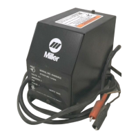
Details the 115 to 24 Volts AC Power Supply Adapter for GMAW wire feeders.

Adapter Output and Input Power

Specifies 24 Volts AC, 8 Amperes output and 110 Volts AC input power.

Protection and Receptacle

Includes overload protection and a 14-socket wire feeder receptacle.

Included Accessories

Lists the included mounting bracket and 115 Volts AC/Remote Contactor Cord.

Safety Symbol Definitions

General Hazard Warning

Indicates potential hazards with procedures, illustrated by adjoining symbols.

Electric Shock Hazard

Warns about electric shock from welding electrode/wiring and advises dry gloves.

Qualified Personnel Requirement

States that only trained and qualified persons should install or operate the unit.

Eye Protection

Advises users to wear safety glasses with side shields.

Installation Onto Wire Feeder

Power Disconnection

Mandatory step: Disconnect power before commencing installation.

Side Brackets Removal

Instruction to remove the side brackets from the wire feeder.

Spool Support Installation

Procedure for installing the adapter into the spool support.

Installation Onto Welding Power Source

Top Mount Installation

Guides for mounting the adapter to the top of the welding power source.

Side Mount Installation

Guides for mounting the adapter to the side of the welding power source.

Mounting Clearance

Ensures the adapter does not obstruct labels or air louvers on the power source.

Connections and Circuit Breaker

115V AC/Remote Contactor Connections

Details on connecting the 115V AC/Remote Contactor Plug and Cord.

Pin Information

Explains pin functions for 24V AC input and contactor control circuits.

Circuit Breaker CB1 Function

Information regarding Circuit Breaker CB1, its function, and reset procedure.

Contact Closure Control Wiring

Instructions for connecting contact closure type contactor controls.

Voltage Application Warning

Caution against applying 115V AC to sources requiring only contact closure.

Troubleshooting

No Weld Output Issue

Addresses the problem of no weld output and provides corrective actions.

Parts List

Component Identification

Lists all available parts with item numbers, part numbers, and descriptions.

Related product manuals