OM-354 Page 11
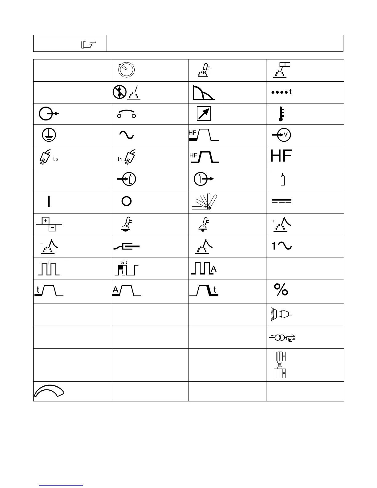
2-3. Symbols And Definitions
Some symbols are found only on CE products.
NOTE
A
Amperes Panel–Local
Gas Tungsten Arc
Welding (GTAW)
Shielded Metal Arc
Welding (SMAW)
V
Volts
Do Not Switch
While Welding
Arc Force (DIG) Spot Timer
Output Circuit Breaker Remote High Temperature
Protective Earth
(Ground)
Alternating
Current
High Frequency -
Start
Input
Postflow Timer Preflow Timer
High Frequency -
Continuous
High Frequency
S
Seconds Gas Input Gas Output Gas (Supply)
On Off Thickness Gauge Direct Current
Balance Control
Maximum
Cleaning
Maximum
Penetration
Electrode Positive
Electrode
Negative
Work Electrode Single-Phase
Pulse Frequency
Pulse Percent
On Time
Pulse Background
Amperage
Hz
Hertz
Start Time Start Amperage Crater Time Percent
U
0
Rated No Load
Voltage (Average)
U
1
Primary Voltage
U
2
Conventional Load
Voltage
Line Connection
I
1
Primary Current
I
2
Rated Welding
Current
X
Duty Cycle
1
1
Single-Phase
Combined AC/DC
Power Source
IP
Degree Of
Protection
I
1eff
Maximum Effective
Supply Current
I
1max
Rated Maximum
Supply Current
Spark Gap
Increase/Decrease
Of Quantity