OM-116 Page 3
SECTION 2 – INSTALLATION
See User’s Guide on unit for process connection information.
NOTE
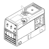
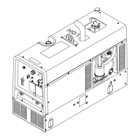
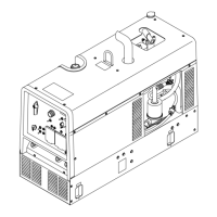
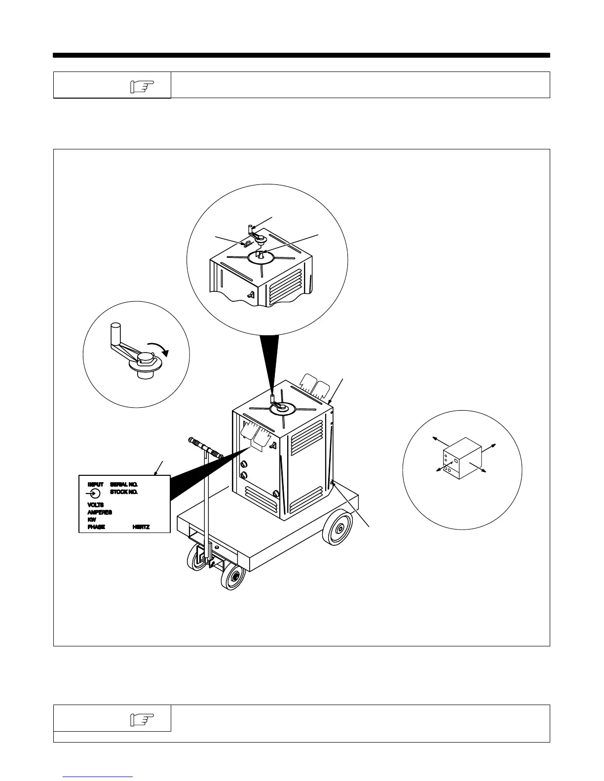
2-1. Selecting A Location And Installing Handle
ST-052 359-D / Ref. ST-151 556 / ST-155 573-A
1 Lifting Area
Place hands where shown to move
unit. Get help when moving unit.
2 Running Gear Mounting Holes
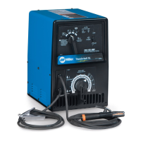
3 Rating Label
Locate unit near correct input
power.
4 Amperage Adjustment Rod
5 Handle
6 Pin
Install as shown.
Move pin into locked position
shown.
1
2
3
Locked Pin
4
5
6
18 in (457 mm) for airflow
2-2. Weld Output Cables
For weld output cable replacements or extensions, contact your Factory
Authorized Service Agent.
NOTE