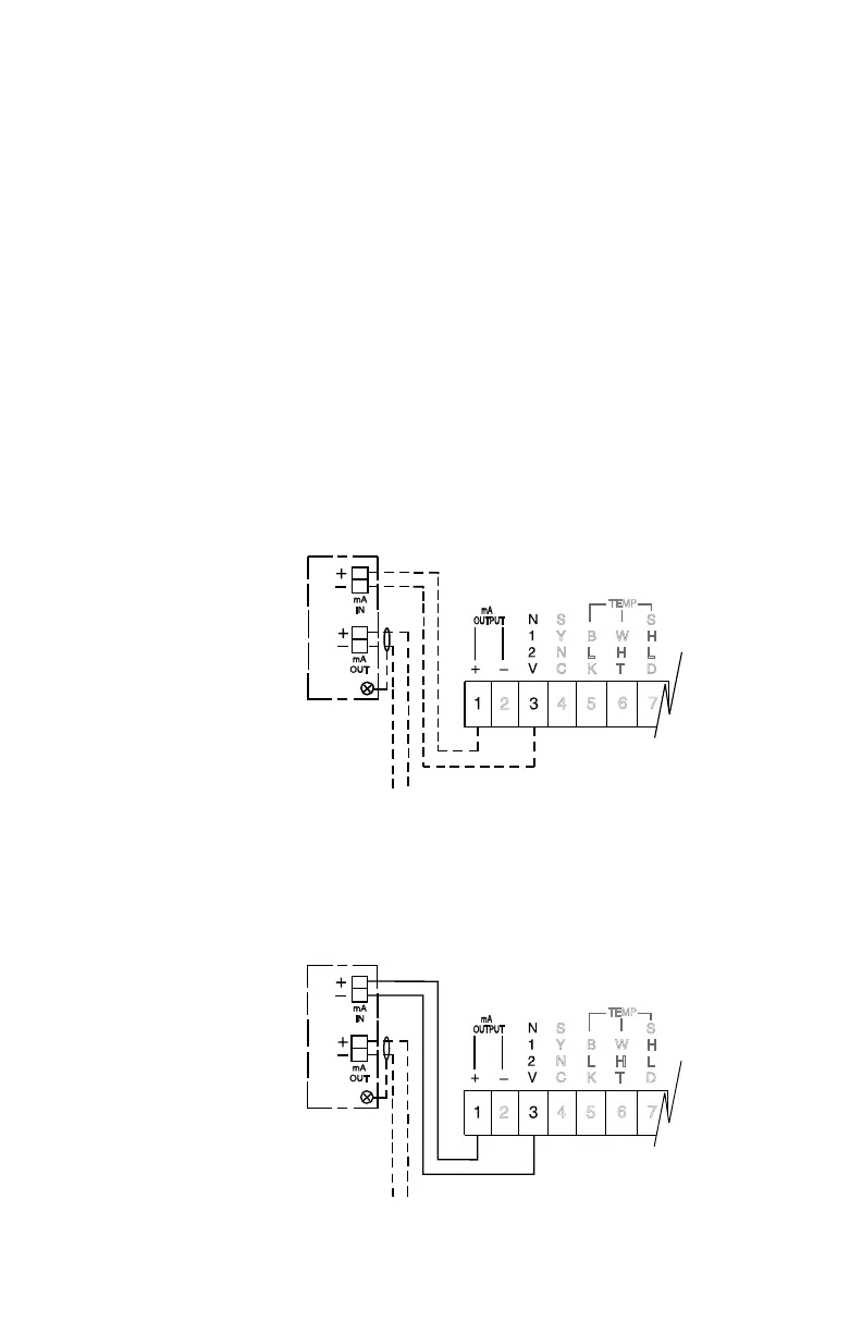
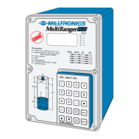
CURRENT OUTPUT ISOLATOR
If the isolator has not been factory installed, mount it on the upper left hand corner of
the motherboard using the two long machine screws provided. The input terminals of
the isolator are then connected to the motherboard output terminals,TB-1, using
twisted pair maximum 16 gauge wire.
Proper shielding and grounding are required in order to minimize noise levels that
could otherwise affect weak receiver signals by introducing false echoes.
The isolator enclosure is grounded by the mounting bolts to the motherboard. This
can be checked with an ohmmeter if a poor connection is suspected.
The isolator output wiring must be a shielded twisted pair. The shield must be
intact up to the isolator and the shield grounded at the isolator mounting screw
only. Do not ground shield at any other point as this will void isolation.
isolated 4 - 20 mA output wiring into 600 Ω max
isolated 4 - 20 mA output wiring into 600 Ω max
Keep shield intact up to output terminals.
Ground shield at screw ONLY!
mA Output - Optional Isolation
(additional to basic wiring)
Route output wiring
cable in separate
conduit, entering
enclosure as near as
possible to isolator.
Keep wiring as short
as possible. Do not
route cable along
terminal board.
Customer Wired
optional
LIs-1
isolator
TB1
Factory Wired
optional
LIs-1
isolator
PL-443 3 – 5