6
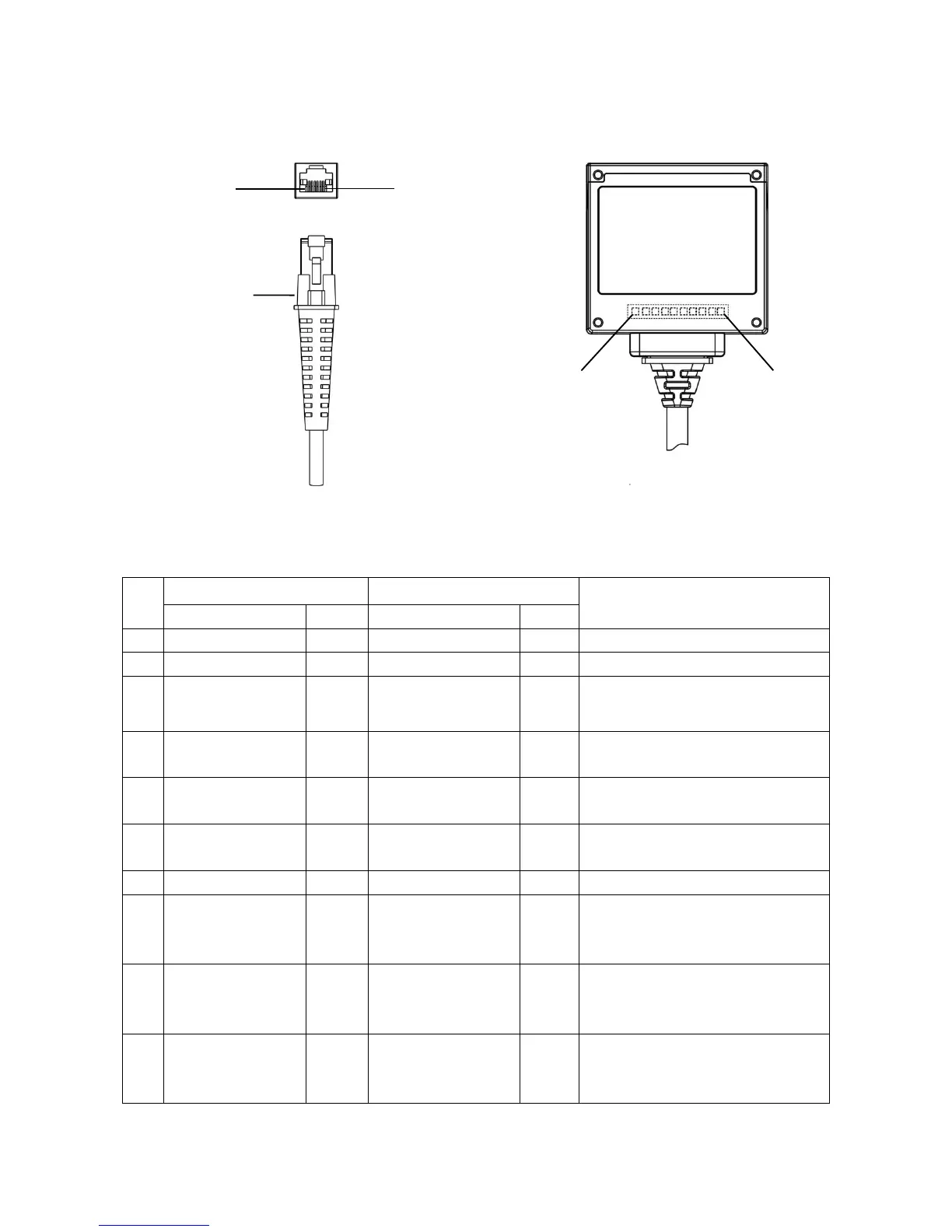
2-2 Electrical interface/Pin assignment of cable connector
The embedded scanner has a RJ-45 cable connector. Table 2-1 lists the pin assignments of the
embedded scanner.
Figure 2-2 Electrical interface/Pin assignment
Table 2-1 Electrical interface/Pin assignment
3.3V (for interface
auto selection)
Ground (for interface
auto selection)
RS-232: Logic high level, 3.3V
USB: Logic low level, 0V reference
RS-232: Serial data transmit output port
(Transmitted data)
RS-232: Serial data receive input port
(Received data)
Logic low level (activity): 0V
referenceLogic high level: 3.3V
RS-232: Handshaking line
(Clear-to-send).
USB: Negative differential line.
RS-232: Handshaking line
(Request-to-send).
USB: Positive differential line.
Note: Voltage level of all RS-232 Pin-outs (RXD, TXD, CTS and RTS) is 0V for logic low level and 3.3V for logic high
level.