Hardware Principle 4-1
4 Hardware Principle
4.1 General Structure of Hardware
System
Main board
IO rear
board
Control panel
Monitor
HDD
I/O signal
+5V/+12V
DVI
DC-DC power
board
SATA
Main
unit fan
Connect to USB port on the
control panel
Control ports
AC-DC
power
board
Battery
module
Main power supply
AC auxiliary output
Isolation
transformer
DVD- RW
probe
connected
assembly
Probe
board
USB
+5V/+12V
CPU
module
Auxiliary output
control
+3.3V
+5V
+12V
+5V
Power supply
Communication &control
Ultrasonic signal
+12V
Rotating feedback & control
BAT+
Communication &
connecting
Transmission
& echo
Transmission
&echo
I/O signal
Machine
fan
+12V
Rotate speed
feedback & control
USB
IO interface board
+12V
Main
unit
module
Power
supply
module
Auxiliary
output control
Speaker
Communication
&control
4D Drive
board
Communication
&control
ECG
board
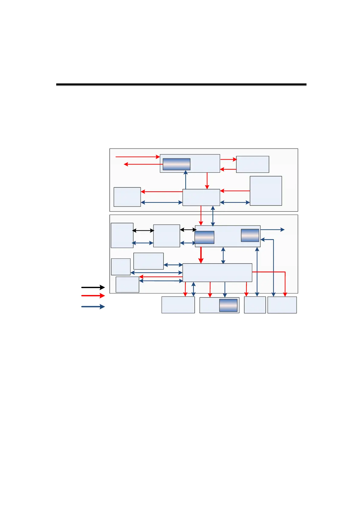
Figure 4-1Schematic Diagram of System
As a mobile color ultrasonic product,the system supports 3 probe sockets.
The detailed structure of the ultrasound system is in the figure above, and they can
be divided into 4 main modules:
Main unit module
Power supply module
Monitor
Control panel
The four modules will be described in the following chapters.
4.2 Main Unit Module
The main unit module contains 7 boards:
Probe board