EasyManua.ls Logo

Mindray DC-32

Mindray DC-32
213 pages
To Next Page IconTo Next Page
Loading...
DC-32/DC-30/DC-28/DC-26/DC-25
Digital Ultrasound System
Service Manual
Revision 11.0

Table of Contents

Questions and Answers:

Mindray DC-32 Specifications

General IconGeneral
Display15-inch LCD
Storage Capacity500GB HDD
Power SupplyAC 100-240V, 50/60Hz
TypePortable Ultrasound System
Image ModesDoppler
Transducer Frequency2-12 MHz
ConnectivityDICOM, Ethernet, USB
Transducer Ports2
ApplicationsObstetrics, Gynecology, Cardiology, Abdominal

Summary

Revision History

Intellectual Property Statement

Applicable for

Specifies that this service manual is for service engineers, authorized personnel, and representatives.

Statement

Describes the product based on the most complete configuration; contact service for questions.

Responsibility on the Manufacturer Party

Customer Service Department

Provides contact information for Mindray's Customer Service Department.

Preface

Meaning of Signal Words

Defines DANGER, WARNING, CAUTION, and NOTE signal words used in the manual.

Meaning of Symbols

Explains safety symbols and warning labels with their meanings and locations.

Warning Labels

Lists and explains various warning labels and their associated meanings.

General Symbols

Details general symbols used in the system, their descriptions, and locations.

Safety Precautions

Provides crucial safety precautions for operating the ultrasound system and probes.

Electric Safety

Outlines essential safety measures related to electrical connections and usage.

Mechanical Safety

Details safety precautions for moving and operating the system to prevent mechanical damage.

Personnel Safety

Specifies safety guidelines for users and authorized personnel regarding system maintenance.

Specifications

Overview

Provides a general overview of the diagnostic ultrasound system.

Intended Use

States the intended use of the diagnostic ultrasound system in clinical settings.

Introduction of Each Unit

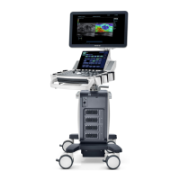
Introduces and illustrates the different units of the ultrasound system.

Peripherals Supported

Lists supported peripherals such as printers and footswitches for the system.

Specifications

Details system specifications including dimensions, electrical requirements, and environmental conditions.

Dimensions and Weight

Provides the physical dimensions and net weight of the ultrasound system.

Electrical Specifications

Outlines the AC input, power consumption, and optional battery specifications.

Environmental Conditions

Specifies the operating and storage/transportation environmental conditions for the system.

Monitor Specification

Details the voltage, dimensions, resolution, and visible angle of the monitor.

System Installation

Preparations for Installation

Covers essential preparations before installing the ultrasound system.

Electrical Requirements

Details regulated power supply and grounding requirements for safe installation.

Installation Condition

Outlines space requirements, network environment, and confirmation steps for installation.

Unpacking

Provides instructions and a sketch for unpacking the main unit package.

Installation of Main Unit

Guides the installation process for the main unit of the ultrasound system.

Display Adjusting

Explains how to adjust the monitor's horizontal position and angle of inclination.

Connecting the Power Cord

Details the procedure for connecting the power cord to the system.

Installing Transducer& Gel Holder

Describes the installation of transducer and gel holders on the system.

Posit the Gel Warmer

Explains where to position the gel warmer based on customer requirements.

Connecting the Transducer

Guides the process of connecting the transducer to the system's probe sockets.

Installing Peripherals

Covers the installation of various peripherals supported by the system.

Footswitch Installation

Provides instructions for installing the footswitch and its system preset settings.

Installing a Graph Text Printer

Details the process of connecting and installing a graph/text printer to the system.

Connecting a Local Printer

Explains how to connect a local printer and check its status.

Add Network Printer

Guides on adding a network printer by configuring its IP address and port.

iStorage UltraAssist Print

Describes printing support using the iStorage function.

Print Service

Explains how to set the default report printer and its attributes.

Installing Printer Adapter

Details the overview and specification of the printer adapter.

Video Printer Installation

Covers the installation of analog and digital video printers.

System Configuration

Guides on configuring the system after installation.

Running the System

Explains how to run the system after connecting power and peripherals.

Enter Doppler

Describes how the system enters Doppler mode after power-on.

System Preset

Details how to access and configure system presets.

Exam Mode Preset

Explains how to set exam modes for different probes.

Measurement Preset

Guides on setting measurement parameters for various modes.

Print Preset

Refers to the chapter for installing graph/text printers.

Network Preset

Details how to configure network settings for the system.

DICOM Preset

Guides on configuring DICOM settings and server information.

System Information

Explains how to check product configuration, software, and hardware details.

Hardware Principle

General Structure of Hardware System

Provides a schematic diagram and overview of the system's hardware structure.

Main Unit Module

Details the main unit module and its constituent boards.

Probe Board

Explains the function and principle diagram of the probe board.

Probe Connected Assembly

Describes the connection between the main board and probe board.

Main board

Details the front-end and back-end structure of the main board.

IO Interface Board

Explains the principle diagram and functions of the IO interface board.

IO Rear board

Lists the ports available on the IO rear board.

ECG Board

Explains the principle diagram and function of the ECG board.

4 D Driving Board

Details the principle diagram and function of the 4D driving board.

Power supply Module

Describes the structure and function distribution of the power supply module.

System Power-on Control

Explains the system power-on control circuit and signal comments.

Monitor

Details the components and functions of the monitor.

Control Panel

Explains the principle diagram and functions of the control panel.

Ultrasound System Monitoring

Describes the system monitoring and temperature monitoring functions.

Ultrasound System Indicator

Explains the principle diagram of ultrasound system indicators.

Function Checking and Testing

Preparation

Outlines the personnel and tool requirements for function checking.

Personnel

Specifies the personnel required for function checking and testing.

Tool

Lists the tools required for function checking and testing.

Checking System Status

Details procedures for checking the system's running status and environment.

System Running Status

Checks if the system turns on/off normally, runs without noise, and displays correct info.

System Running Environment

Checks ambient temperature and humidity for system safety features.

General exam

Provides a general exam check flow and content for the system.

Check Flow

Outlines the check flow for general system examination.

Checking Content

Details the checking content for the control panel, LCD, and peripherals.

Check Control Panel

Checks the functions of keys, knobs, and trackball on the control panel.

Check the LCD

Details how to adjust LCD brightness, contrast, and check its display quality.

Peripheral Device Checking

Checks functionality of peripherals like footswitch, video printer, and graph/text printer.

Check ECG Module

Explains how to check the ECG module's functionality and display.

Checking IO Interface

Describes the checks for VGA interface, network port, and USB port.

Function Checks

Provides a note on comprehensive function inspection based on system configuration.

Check Flow

Outlines the check flow for different imaging modes.

Checking Content

Details the checking content for B Mode, including parameters and adjustments.

B Mode

Details B Mode parameters and adjustments for image optimization.

M Mode

Details the checking content for M Mode, including parameters and adjustments.

Color Mode

Details the checking content for Color Mode, including parameters and adjustments.

PW Mode

Details the checking content for PW Mode, including parameters and adjustments.

Cine Review

Explains how to review cine images and enter cine status.

Measurement

Guides on performing measurements in different modes and exiting the measurement function.

Patient Information Management

Describes how to save, review, and manage patient information.

Performance Test

Outlines the test process for evaluating system performance.

Test Process

Details the steps involved in performing performance tests.

Test Content

Lists the requirements and tips for testing system performance.

Resolution

Explains the test steps for transverse and axial resolution.

Maximum Depth

Provides test steps for determining the maximum depth of the system.

Geometric positioning accuracy

Details test steps for longitudinal and transverse geometric positioning accuracy.

Blackout Area

Provides test steps for measuring the blackout area of the system.
Structure and AssemblyDisassembly

Structure of the Complete System

Shows an exploded view of the complete ultrasound system.

Field Replaceable Unit

Lists the field-replaceable units (FRUs) of the system with part numbers.

Preparation

Outlines necessary tools and engineer requirements for disassembly.

AssemblyDisassembly

Provides a schematic of assembly/disassembly sequences and notes.

Monitor assembly

Details the steps for disassembling and removing the monitor module.

IO Rear Board

Guides on disassembling the IO rear board.

Machine Fan

Provides steps for disassembling the machine fan.

Power Input Assembly

Details the procedure for removing the power input assembly.

Power Module Assembly

Guides on disassembling and removing the power module assembly.

Main Unit Box Module

Details the steps for disassembling the main unit box module.

Main Unit Fan

Explains how to remove the main unit fan.

IO Interface Board

Guides on disassembling the IO interface board.

Probe Connected Assembly and CPU Module Assembly

Details removing probe connected assembly and CPU module assembly.

Main board assembly

Guides on removing the main board assembly.

4 D Module

Details the steps for disassembling the 4D module.

ECG Module

Provides steps for disassembling the ECG module.

Probe Board Assembly

Guides on assembling and disassembling the probe board.

Left Side-Panel Assembly

Details the steps for removing the left side-panel assembly.

Right Side-panel Assembly

Guides on removing the right side-panel assembly.

Control Panel Assembly

Details the steps for disassembling the control panel assembly.

Singledual-encoder Board

Explains how to remove single/dual-encoder boards.

TGC Board

Guides on disassembling the TGC board.

Trackball

Details how to remove the trackball.

Keyboard Top Cover Assembly

Guides on disassembling the keyboard top cover assembly.

Buzzer

Explains how to disassemble the buzzer.

USB Adapter Board

Guides on removing the USB adapter board.

DVD Assembly

Details the steps for disassembling the DVD assembly.

Others

Introduces other components for disassembly.

Spring assembly

Guides on disassembling the spring assembly.

Cable of the main unit

Details the steps for removing cables of the main unit.

Isolation Transformer

Guides on disassembling the isolation transformer.

Hard Disk

Details the steps for disassembling the hard disk.

Battery Assembly

Guides on disassembling the battery assembly.

Options Installation

Installation of Optional Devices

Covers the installation of optional software devices and modules.

Installation of Hardware Optional Function

Lists hardware optional functions and their installation references.

Printer Adapter

Details the structure, tools, and requirements for the printer adapter.

Structure of the Entire System

Shows the structure of the printer adapter system.

Tools Required

Lists the necessary tools for printer adapter assembly/disassembly.

Engineers Required

Specifies the required personnel for printer adapter maintenance.

Requirements

Outlines preparations needed before disassembling the printer adapter.

AssemblingDisassembling

Provides steps for assembling and disassembling the printer adapter.

System Diagnosis and Support

General Status Indicator

Explains the status indicators on the control panel.

The Status Indicators on the Control Panel

Details the status indicators for power, battery, AC, and hard disk.

The Status Indicators of the Power on the IO Rear Board

Describes power status indicators on the IO rear board and system status.

Starting Process of the Whole System

Illustrates the system startup process with key indicators.

Start Process of Complete System

Details startup procedures when powered by AC or battery.

Powered on by AC

Details startup procedures when the system is powered on by AC supply.

Powered on by Battery

Details startup procedures when the system is powered on by battery.

The start-up Process of BIOS

Describes the BIOS start-up process.

The Start-up of Linux

Explains the Linux start-up process.

The Start-up of Doppler

Outlines the procedure and details for Doppler startup.

Procedure of Startup

Details the startup procedure for the Doppler function.

Alarming and Abnormal Information

Covers system alarming functions and abnormal information logging.

Turning on the System Configuration File is Abnormal

Describes the cause and suggestion for abnormal system configuration files.

The voltage of system power is abnormal

Details alarming tips, log records, and suggestions for abnormal system power voltage.

Temperature Alarming

Explains temperature alarming, log records, and suggestions for different sensors.

Fan Alarming

Details alarming tips, log records, and suggestions for fan-related issues.

Battery Alarming

Lists alarming tips, log records, and suggestions for battery-related issues.

PHV Related Alarming

Details alarming tips, log records, and suggestions for PHV-related issues.

Care and Maintenance

Overview

Recommends procedures for care and maintenance.

Tools, Measurement Devices and Consumables

Lists necessary tools, measurement devices, and consumables.

Care and Maintenance Frequency

Provides a table detailing the frequency and method for care and maintenance tasks.

Cleaning the System

Outlines the flow of cleaning and content for various system parts.

Flow of Cleaning

Illustrates the step-by-step process for cleaning the ultrasound system.

Content

Details the cleaning methods for the power button, monitor, and touch screen.

Cleaning Power button

Details cleaning methods for the power button.

Monitor and Touch Screen

Details cleaning methods for the monitor and touch screen.

Cleaning Trackball

Details cleaning methods for the trackball.

Cover and control panel

Details cleaning methods for the cover and control panel.

Cleaning Probe

Details cleaning methods for the probe and probe holder.

Maintenance Check

Outlines the process for performing maintenance checks on the system.

System Function

Lists system functions to be checked, including B mode, M mode, and others.

Peripherals and Options Check

Details checks for peripherals like printers, footswitches, and DVD-RW.

System Maintenance

Covers system maintenance procedures.

Electrical Safety Maintenance

Refers to Appendix A for electrical safety inspection.

Mechanical Safety Maintenance

Explains checking mechanical strength and function of key assemblies.

Troubleshooting of Regular Malfunctions

System cannot be powered on

Addresses issues related to the system not powering on.

System Cannot Start up Normally

Discusses troubleshooting steps when the system fails to start up normally.

Image Fault

Covers troubleshooting for common image faults like dark strips and noise.

Probe Socket System Malfunction

Addresses issues related to probe socket recognition and malfunction.

IO Interface System

Discusses troubleshooting for the IO interface system, including ports and speakers.

Control Panel

Covers troubleshooting for the control panel, including keys and trackball.

Troubleshooting

Details troubleshooting steps for control panel key failures and trackball issues.

Monitor

Addresses troubleshooting for monitor issues like display and backlight.

Troubleshooting

Details troubleshooting for monitor display problems and mode key indicators.

Printer Adapter Related Troubleshooting

Provides troubleshooting steps for printer adapter connectivity and printing failures.

Appendix A ELECTRICAL SAFETY INSPECTION

Appendix A ELECTRICAL SAFETY INSPECTION

Introduces recommended electrical safety tests for comprehensive maintenance.

Appendix A ELECTRICAL SAFETY INSPECTION

Details test procedures for the power cord plug and its components.

Appendix A ELECTRICAL SAFETY INSPECTION

Covers visual and contextual inspections of the device enclosure and accessories.

Appendix A ELECTRICAL SAFETY INSPECTION

Details checks for the presence and legibility of device labels.

Appendix A ELECTRICAL SAFETY INSPECTION

Explains the procedure for testing protective earth resistance.

Appendix A ELECTRICAL SAFETY INSPECTION

Details the procedure for performing earth leakage tests.

Appendix A ELECTRICAL SAFETY INSPECTION

Explains the procedure for measuring patient leakage current.

Appendix A ELECTRICAL SAFETY INSPECTION

Details the procedure for testing mains on applied part leakage.

Appendix A ELECTRICAL SAFETY INSPECTION FORM

Provides a form for recording inspection and testing results.

Appendix B Phantom Usage Illustration

Appendix B Phantom Usage Illustration

Illustrates the target disposal and line target system of the phantom.

Appendix C Requirements of Performance Indices

Appendix C Requirements of Performance Indices

Lists performance index requirements for various probe models.

Appendix D Boot Screen

Appendix D Boot Screen

Shows illustrations of the BIOS and LINUX boot screens.

Appendix D Boot Screen

Shows the illustration of the Doppler boot screen.

Related product manuals